It is time that I revisit the 2 year old Multi-LED Joule Thief. This time I want to make some improvements for not only efficiency but ease of assembly since I plan on making about 4 times as many as last time.
The Components
2 Line Common Mode Choke
The previous version used a hand wound toroidal transformer. I had found while completing the Joule Thief Candle that a 2 line SMD common mode choke could be used in place of the hand wound transformer saving significant assembly time.
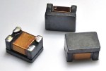
The only downside is that the choke is a little pricy at $0.50 each making it the most expensive component of the whole product. I reordered the same model common mode choke and also a few others from the same manufacture to try. Below is a table of the chokes I purchased along with the original and results of building a joule thief circuit on a breadboard with them.
| Part Number | Result |
|---|---|
| Bourns SRF4532-510Y | Original, works |
| Bourns SRF2012-900YA | does not work |
| Bourns SRF3216-222Y | does not work |
In picking common mode chokes to experiment with I stuck with the Bourns SRF family hoping that since I know at least one of them works in the joule thief circuit that another lower cost one would but this turned out to be wrong. I do not know what makes one choke work over all the others and more importantly how I chose the only working choke the first time. To offset the high price I upped my order quantity and was able to get a unit cost of $0.32 at quantities of 500 or greater from Digi-Key.
SMD LEDs
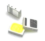
I wanted to switch to surface mount LEDs for this version so I ordered the Luminus Devices MP-2016-1100-65-70, a cool white 6500K LED in an 0806 SMD package. These LEDs are super bright at 144 lm/W. I am able to replace the original 17 3mm LEDs with just 6 of these new LEDs while still being brighter.
Power Switch and Battery Clip
I tried in frustration to get the original 3D printed power switch to work but didn’t have any luck. Looking back though my order history the original version used the 12BH092-GR from Eagle Plastic Devices. Supply issues when designing the Joule Thief Candle caused me to switch to the BK-92 from Memory Protection Devices which have a slightly different geometry and do not work with the 3D printed power switch. I have such a large supply of BK-92 left over from the Joule Thief Candle that I am unlikely to switch back to the original battery clips.
Since I can’t use the 3D printed switch I needed to place a power switch on the PCB. I was familiar with the OS102011MA1QN1 slide switch from C&K since it is used on the Joule Thief Candle. Space constraints on the PCB required that the switch be placed on the PCB above one of the battery clips.

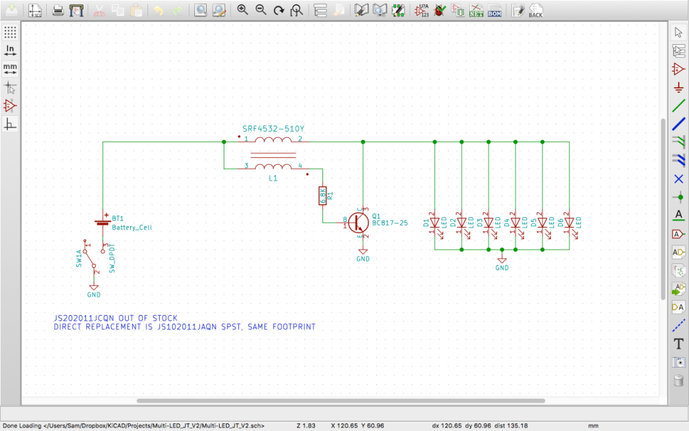
This causes the pins of the switch to interfere with the footprint of the battery clip. Using a SMD switch would eliminate this problem. I originally designed in the JS202011JAQN DPDT SMD right angle slide switch but after completing the PCB layout and ordering a set of PCBs from OSHPark I realized the switch was now out of stock with a 7 week lead time. Looking through the JS Series Datasheet the JS102011JAQN SPDT slide switch uses the same footprint, problem solved.
NPN Transistor and Resistor
I stuck with the BC817-25-TP NPN transistor used in the original Multi-LED Joule Thief and the Joule Thief Candle since it works and I purchased enough of the them to make hundreds of units. Using the findings from my previous post Joule Thief Measurements: Base Resistor I changed the base resistor value from 1K to 6.8K.

The PCB
The size of the original PCB remained the same along with the placement of the battery clips. The new SMD components remained close to the original placement of the components they replaced. For ease of layout the power switch disconnects the ground of the circuit instead of the positive.
The silkscreen for the battery changed slightly to be more similar to the silkscreen on the Joule Thief candle with indication of the battery type to be installed.

After layout a set of three PCBs were ordered from OSHPark to confirm the circuit would work and I didn’t make any goofs before ordering a larger quantity.

For a larger batch of PCBs I tried a new to me board house JLCPCB which was slightly cheaper then my go to board house PCBWay. The JLCPCBs work and look ok but boards form PCBWay have a much better quality of silkscreen and are manufactured quicker. I think I will stick with PCBWay after using up the PCBs from JLCPCB.

Assembly
Looking for a challenge and always making silly changes I decided to switch to lead-free solder and solder paste. It is not as difficult as I was lead to believe based on forum posts and YouTube videos, the key is a slightly higher heat setting on my soldering iron (395C) and solder with a good amount of resin.
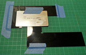
Learning from assembly of the original Multi-LED Joule Thief and also from the Joule Thief Candle I finally purchased a solder paste stencil from OSH Stencils, this is something I should have done a long time ago since it speeds up application of solder paste so much for such little cost.
Usually with SMD parts I can get away with using a SMD reflow hot air station to reflow the solder paste but I found that the SMD switch was easily melted by the hot air. Needing a better way to control the temperature I purchased a Controleo3 conversion kit to turn a toaster oven into a reflow solder oven.

A slight adjustment of the default soldering profile to prevent discoloration of the white solder mask and I can now reflow 20 or more PCBs in less than 10 minutes cutting my assembly time down even more. Now the most time consuming task is placement of the SMD components followed by soldering of the only thorough hole components, the battery clips.
Flux residue is removed from the board after soaking it in 4140-P flux remover. Previously I was using 90% Isopropyl Alcohol but found it was slow and still left flux residue requiring scrubbing with a ESD safe brush.
Design Files
The design files for the Multi-LED Joule Thief can be found in the following GitHub repository https://github.com/sdp8483/Multi-LED_JT_V2
Design updates in the future will be pushed to that repository. The KiCAD schematic is fully annotated with component part numbers, all components are available at the time of writing from Digi-Key. PCB gerber files are included in the repository for replication of the PCB.
The repository also includes photos of fully assembled PCBs and datasheets for most of the components.
Buy Assembled Multi-LED Joule Thief


If you don’t wish to go through the hassle of manufacturing your own Multi-LED Joule Thief they are available for sale (along with the Joule Thief Candle) through Tindie here: https://www.tindie.com/products/10989/
View other related Joule Thief articles.


Hi Sam,
I am curious do you think this would be bright enough to put in a lantern for decorative lighting purposes? I want to 3d print a lantern designed around this and was wondering if you would do any price breaks for greater quantities? Please feel free to reach out to me. Thanks
LikeLike
It should be bright enough for decorative needs. My only concern is that battery life is about 100hrs so leaving these on for long extents of time will drain batteries quickly. It is not a particularly efficient circuit. For outdoor applications you cannot go wrong with the solar cell and NiCad battery. I think there is an all in one IC for that application but you will have to search around.
As far as large quantities I would suggest you look at making these yourself, the PCB files are on GitHub if you want to go that way or you could always start with protoboard and see where that takes you. There may be things you can tweak to get more battery life or brighter light. I have a few posts on measuring battery life and brightness you could start with.
Thanks and best of luck with your project.
LikeLike
Just an idea to add additional usability to an already great setup.. I was thinking it would be great if there is a way to maybe add a spring the the negative side terminal so it could use aa and aaa batteries. Also, would there be a way of ordering this as a diy kit? I’m rekindling my enjoyment of electronic tinkering n luv assembling things myself. And was playing around with the idea of modifying this to fit into a flashlight housing i have.
I look forward to hearing from you, thx joe
LikeLike
Glad to see your interest into electronic tinkering. Selling this as a kit would not be possible since the LEDs can only be soldered using a re-flow oven but have you looked at my original Multi-LED Joule Thief? The link to that is at the top of the page.
That design could totally be made at home without any need for a kit. I suggest making it on a prototype PCB and experimenting. Its a fun thing to do and is one of the reasons I got hooked on hobby electronics. I was inspired by BigClive’s video on YouTube for the small transformer so check out his video: https://www.youtube.com/watch?v=K53beWYdIpc
Thanks for your comment!
LikeLike