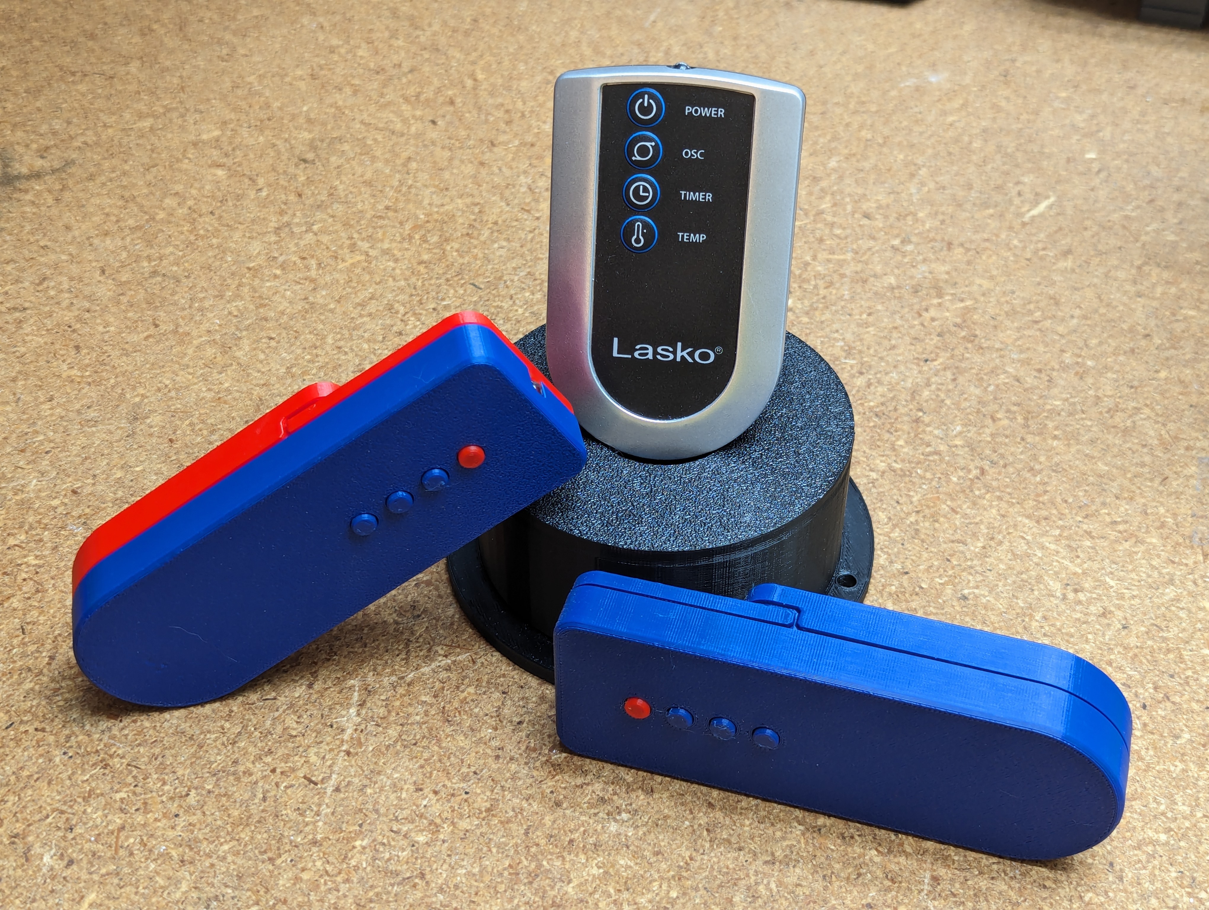
In the middle of a 2023 upstate NY heatwave I picked up a pedestal fan. While shopping for one at the local big box store I was given the option of getting a simple fan or, for a few dollars more, an upgraded fan with more features. I went with the upgraded fan with the assumption that I would not use most of the features but for the price difference there was no reason not to. One of the features I though that would not be useful was the included remote control, I was very wrong about that and would say that in the future I wouldn’t buy a pedestal fan without a remote. My only complaint about the remote is that the fan comes with only one so in order to be able to control the fan throughout my apartment I needed to carry the remote around with me. I looked into getting a second remote but Lasko does not sell one and there was no 3rd party manufactures offering a remote. The closest I found to getting a second remote was used items on eBay that cost almost as much as I paid for the fan and remote. Looking to save some money I set about designing my own remote and in the end I was able to make not just one, but two remotes to leave laying around my apartment at common points so that fan control was always within reach.
Signal Decoding
The first part of this project was to reverse engineer the Lasko remote, specifically the IR signal that is used to control the fan. That involved probing the IR diode with a logic analyzer while pressing the buttons to understand the signal.
The remote sends signals to the fan using an infrared LED. This IR LED is connected to the GPIO of a microcontroller so that when the GPIO pin is pulled low the IR LED is turned on.
Carrier Frequency

The IR LED sends the signals using a carrier frequency of 38kHz. This seems to be a popular frequency for most consumer IR remotes. Bits are sent as a duration of pulsing the IR LED at the carrier frequency followed by a period of no IR. All bits are 1680us long.
Signal Bit Value of One

I’m calling the above bit as having a value of one. I have no way of knowing if the remote and fan consider this value to be a one but it doesn’t matter since this designation is used only as a shortcut in my firmware to encode the signals. This bit is 1680us long with 1246us of IR LED pulsing followed by no IR for the remainder of the bit.
Signal Bit Value of Zero
The above bit has a value of zero. Again this bit is 1680us long with 404us of IR LED pulsing followed by no IR for the remainder of the bit.
Power Signal
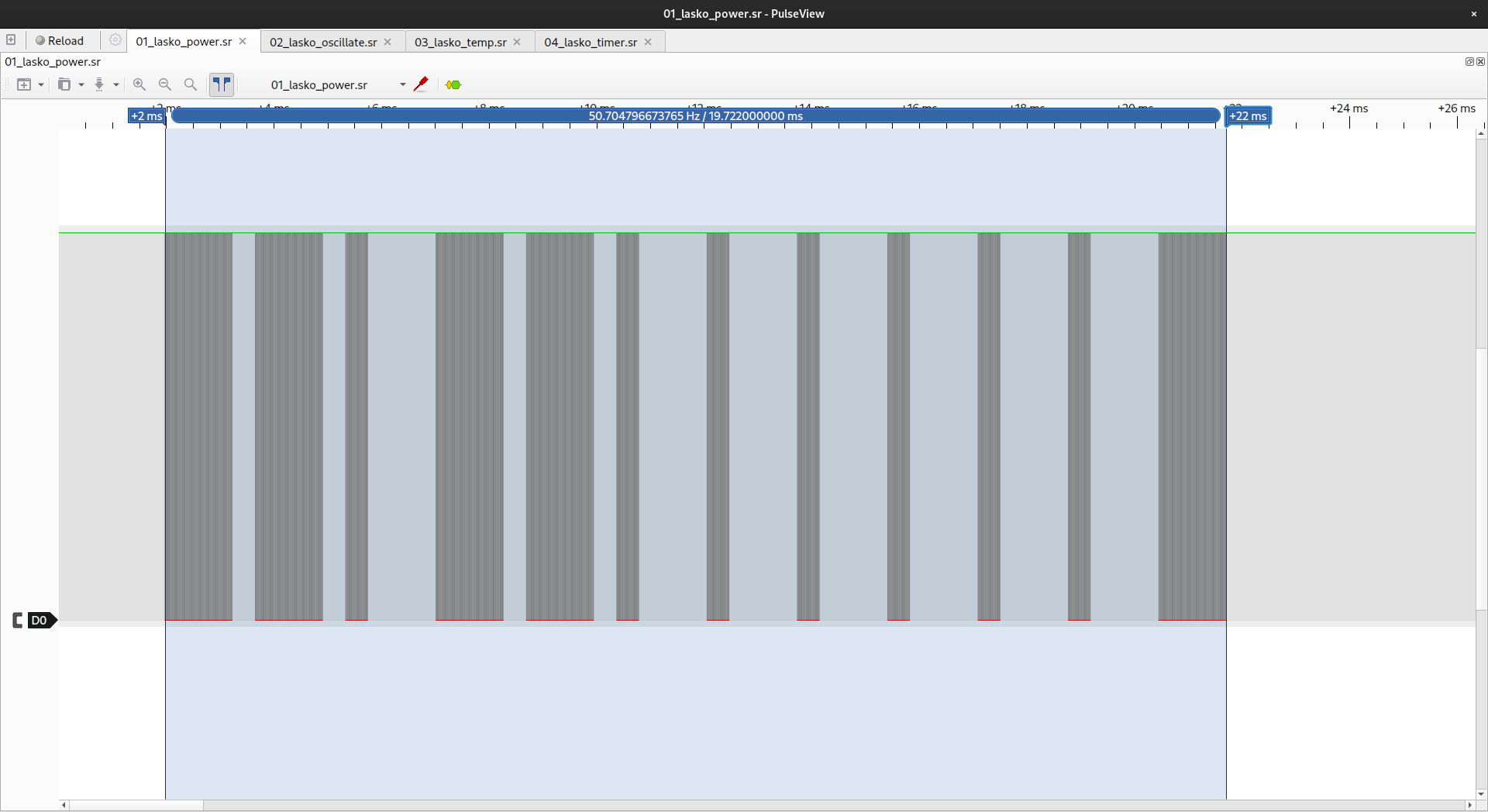
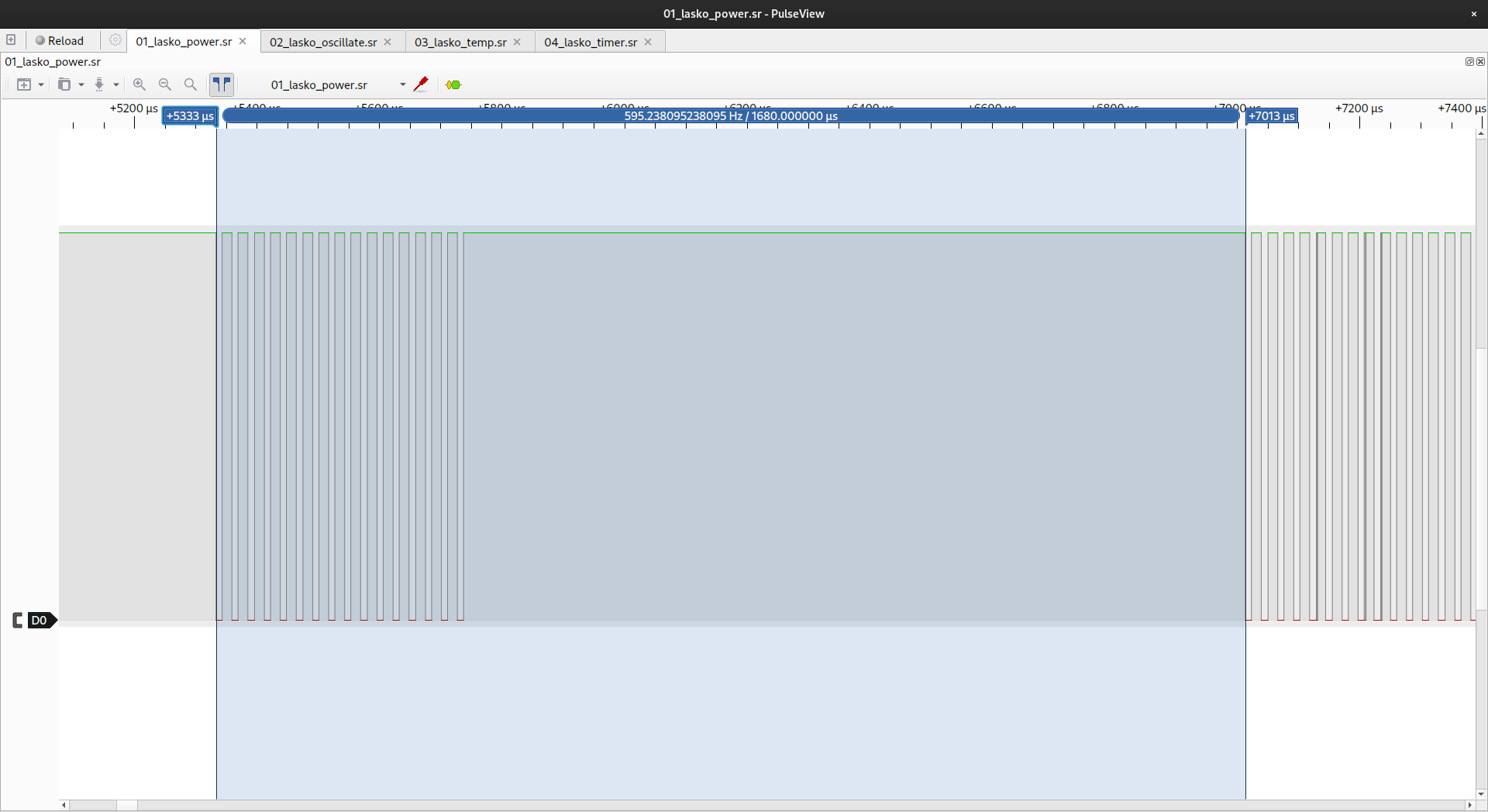
The remote strings together the one and zero bit values to send out commands. Following the bit value convention outlined above the logic capture of the power signal is 0b110110000001. All signals are 12 bits long and repeat 4 times with a delay of 7107us between repeats. The power signal from the remote will turn on the fan if it is off and decrement through the four fan speeds with each press until turning the fan is off again.
Oscillate Signal

The oscillate signal is 0b110110000010. The oscillate signal will enable and disable the oscillation of the fan.
Temperature Signal

The temperature signal is 0b110110010000. This signal is used to set a turn off temperature for the fan from 60F to 80F in 5F increments. If the ambient temperature drops below this setting the fan will turn off.
Timer Signal
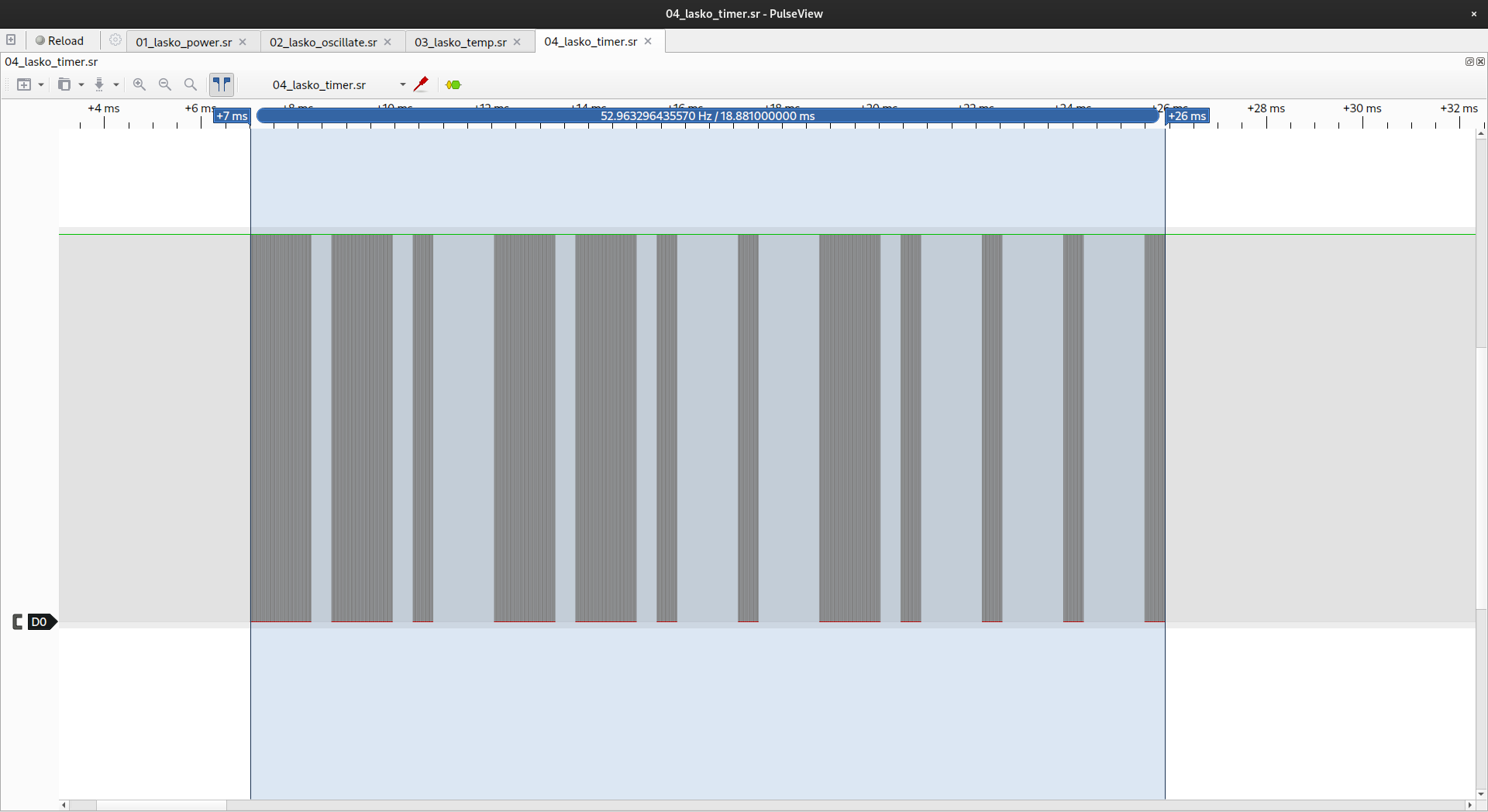
The timer signal is 0b110110001000. This signal sets a timer to turn the fan off. Interestingly the timer value is displayed as a binary value. There are LEDs for 1, 2, and 4 hours on the fan. By pressing the timer button the timer will increment from 1 to 7 hours.
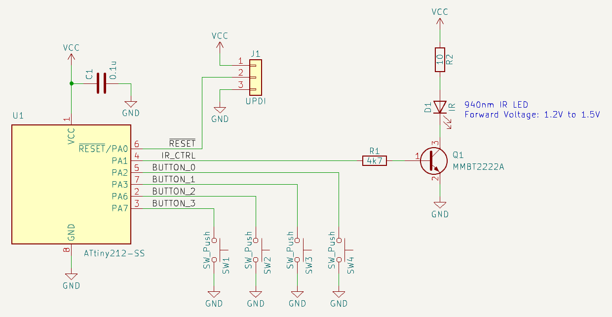
Schematic
There is nothing ground breaking about the circuit I came up with. The heavy lifting is done using my favorite microcontroller for small projects, the Attiny212. The hardest part about this circuit was finding what IR LED to use, I found 940nm to be the correct wavelength.
Firmware
The microcontroller spends much of its time asleep to save power. All four buttons are used as an interrupt to wake the Attiny212. The carrier frequency is generated using Timer A on the Attiny212. The timer ISR will toggle the IR LED for the required duration and then the IR LED will be turned off for the remainder of the bit. Again to save power the Attiny212 is allowed to sleep in between pulses. The full code can be found here: https://github.com/sdp8483/lasko_ir_remote/blob/master/firmware/src/main.cpp
PCB
Since I only wanted to make two extra remotes I decided to make the PCBs at home using my CNC 3018 Pro Router.

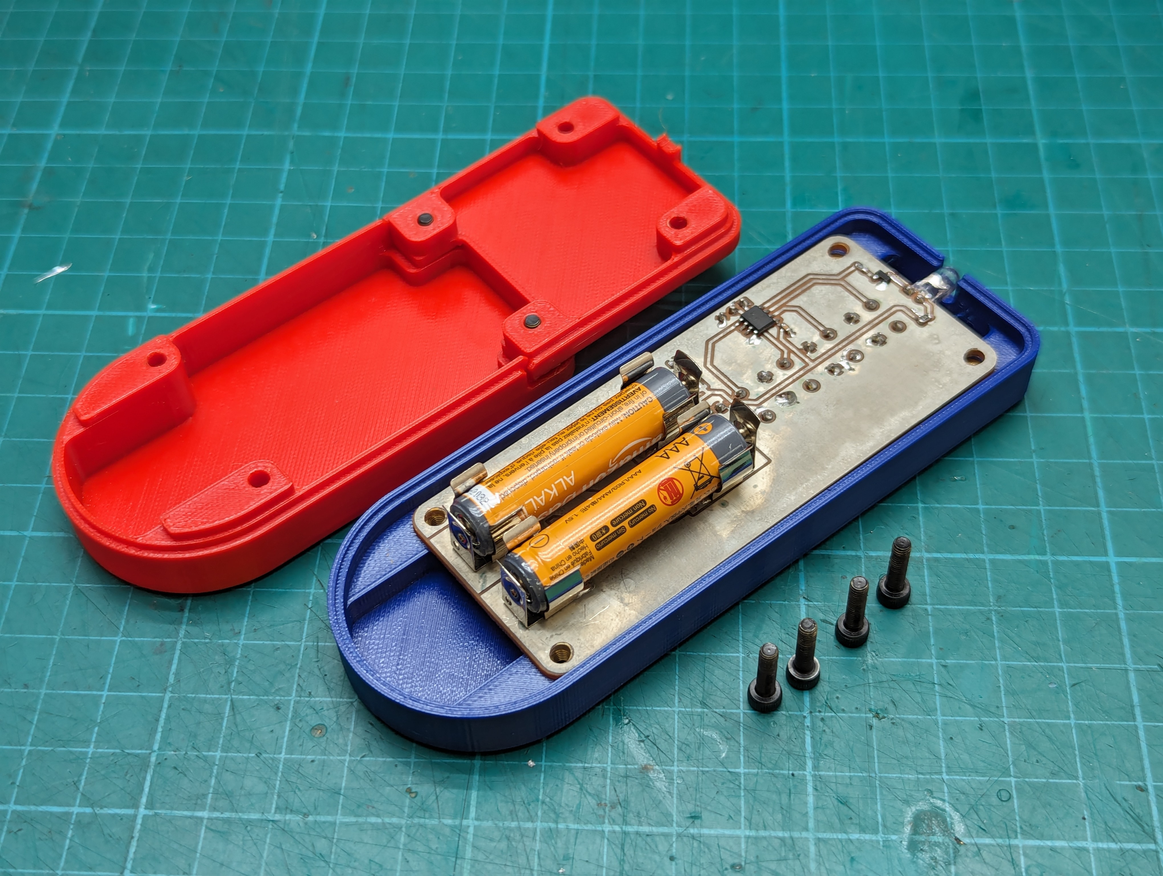

Enclosure
For the enclosure I went with a 3D printed three piece design. The enclosure is held together with 10mm long M3 socket head bolts. I have threaded inserts to make battery changes easier.


Conclusion
This was an easy project to make with the most difficult part being finding the correct wavelength of IR LED to use. I initially used a 850nm IR LED but I found that while the signal would be received by the fan, the remote had to be pointing directly at the fan and I had to be standing within arms reach for it to work. The 940nm IR LED was found to work much better.
The final hardest part of this project was that I completed this PCB and firmware about 6 months ago and only now have gotten around to writing this documentation up. I have forgotten much and have had to gloss over many of the details in this documentation.
All the design files and firmware can be found in the following Github repository: https://github.com/sdp8483/lasko_ir_remote/tree/master

such great timing for you to share this project. I am about to build an IR emmiter using a tinyAVR.
I plan to analyze the power savings from SLEEP_MODE_IDLE between every microsecond of each pulse.
LikeLike
Cool, you lost me after paragraph three, hee hee, soon you’ll be needing that fan, but not today 12° here, burr.
have a good day Sam
LikeLike