The Crazy Cruiser cat toy by SmartyKat is not so smart. The toy is the cat equivalent of a simple bristle bot. It consists of a power switch, LED, and vibration motor all powered by two LR44 coin cells. To activate the toy for cat play time a human is required to turn the toy on. During playtime it runs at a constant vibration speed and the light doesn’t even blink! Not that smart. This also means that when kitty gets tired of playing (if a kitten can get tired please let me know) the toy will continue to run and drain the batteries. I aim to fix that by making the toy smarter.

Simple and minimal parts will be used to smarten up this toy, after all it is still a low cost cat toy. This will be accomplished by adding a vibration switch and a microcontroller. The vibe switch will be used to wake up the uC from deep low power sleep in which the uC will start the vibration motor and LED. The toy will then remain active for a set amount of time then turn off to be activated later.
Current Measurements and Getting Inside
Before improving the battery life of this toy I wanted to see what the current draw was of the not so smart version. Under battery power I measured 35mA with the batteries at around 2.47V.
To get a current curve at different voltages it was easier to open up the toy so that I could clip on test leads. The plastic housing is glued together at the seam. A small vise made quick work of opening this up.


I measured the following current draw at voltages from 2V to 3V.
| Voltage [Volts] | Current [mA] |
| 3.0 | 51.0 |
| 2.8 | 44.1 |
| 2.6 | 38.8 |
| 2.4 | 32.1 |
| 2.2 | 26.5 |
| 2.0 | 21.0 |
Schematic

Nothing complicated about the schematic. A few things to point out about why I chose the parts I did.
- First I am using only components that I have on hand, I did purchase the SW-18001P vibration switch but everything else is what I can find in my stash or is reused from the original toy components.
- I use a P-channel MOSFET for reverse polarity protection because it introduces the lowest voltage drop. A shottky diode would be about 0.2V. The datasheet for the NCE3401 does not directly show what the Rdson at currents lower the 1A would be but extrapolating it looks to be around 75mΩ. At the maximum current draw of this circuit of 51mA that would be a voltage drop of 3.8mV.
- To reduce BOM count I am using the same P-channel MOSFET that is used for reverse polarity protection to also switch the rumble motor. I could just as easily use a N-channel or NPN transistor.
- I have been playing around with the Padauk PFS154-S08 for the last few weeks so I would like to use it in a project. This microcontroller will run from 2.0V~5.5V so it covers the usable range of the LR44 batteries. This model of the famous 3¢ microcontroller is multi-programmable (so double the cost, big spender here).
Go To (Deep) Sleep!
I wrote some code for the PFS154-S08 using interrupts to wake the uC using the vibration switch, turn on the LED and motor for a few seconds and then turn everything off and go into deep sleep. This was simple code to make sure my code structure would work and then I would build on it for more complicated features such as blinking the LED and PWMing the motor. Everything was going just fine with the vibration switch waking up the uC and the LED and motor turning on and off as expected. The only issue I found that was when the uC was set to deep sleep it was drawing around 50uA.
The datasheet for the PFS154 claims a typical deep sleep using stopsys should consume around 0.5uA (pg. 16). I suspected that for some reason the uC was not going into deep sleep so I wrote some super simple code that setup the uC similar to how I had it setup but went into stopsys before reaching the forever loop. The current draw was still higher then the datasheet. I wanted the uC to go to sleep and I suspected that it was not.
To prove to myself that it was not going into sleep I wrote the following code that toggles a PIN in a while loop after a call to stopsys. Since I don’t have any wake pins enabled the uC should never reach the pin toggling code.
/* Go To (Deep) Sleep! V1
 *  testing the deep sleep of the PFS154-S08
 *  compiled using free-pdk
 */

#include <stdint.h>
#include <pdk/device.h>
#include "auto_sysclock.h"

// Pin Defines - all pins are on port A
#define PIN   3

// Output Pin Function Defines
#define PIN_TOGGLE()  PA ^= (1 << PIN)

// Main Program
void main() {
  MISC |= MISC_FAST_WAKEUP_ENABLE;  /* enable faster wakeup, 45 ILRC clocks instead of 3000 */

  PADIER = 0;                       /* on reset all pins are set as wake pins,
                                       setting register to 0 to disable */

  PAC |= (1 << PIN);                /* set pin as output */

  __stopsys();                      /* go to deep sleep */

  // forever loop - code execution should never reach this
  while(1) {
    PIN_TOGGLE();

    // simple delay
    for (int16_t i=0; i<1000; i++) {
      __nop();
    }
  }
}

// Startup code - Setup/calibrate system clock
unsigned char _sdcc_external_startup(void) {
  /* Set the system clock
   * note it is necessary to enable IHRC clock while updating clock settings or CPU will hang  */
  PDK_USE_ILRC_SYSCLOCK();          /* use ILRC 55kHz clock as sysclock */
  PDK_DISABLE_IHRC();               /* disable IHRC to save power */
  EASY_PDK_CALIBRATE_ILRC(F_CPU, TARGET_VDD_MV);

  return 0;   // Return 0 to inform SDCC to continue with normal initialization.
}
To my surprise when I probed PA3 it was toggling and my current draw was again ~50uA. Why wont you go to sleep!
When I first started playing around with the PFS154-S08 I found a project for an Ultra Low Power LED Flasher using the PFS154. I remembered that in that code the author also disabled the wake function on port B since it would cause the uC to wake even though there is no port B on the -S08 variant of the PFS154. So with the modified code below I was finally able to get the uC to go to (deep) sleep with a current draw of around 0.3uA at Vdd=3.0V.
/* Go To (Deep) Sleep! V2
 *  testing the deep sleep of the PFS154-S08
 *  compiled using free-pdk
 */

#include <stdint.h>
#include <pdk/device.h>
#include "auto_sysclock.h"

// Pin Defines - all pins are on port A
#define PIN   3

// Output Pin Function Defines
#define PIN_TOGGLE()  PA ^= (1 << PIN)

// Main Program
void main() {
  MISC |= MISC_FAST_WAKEUP_ENABLE;  /* enable faster wakeup, 45 ILRC clocks instead of 3000 */

  PADIER = 0;                       /* on reset all pins are set as wake pins,
                                       setting register to 0 to disable */
  PBDIER = 0;                       /* there is no port B on the -S08 package,
                                       without setting this to 0 the uC will wake unexpectedly */

  PAC |= (1 << PIN);                /* set pin as output */

  __stopsys();                      /* go to deep sleep */

  // forever loop - code execution should never reach this
  while(1) {
    PIN_TOGGLE();

    // simple delay
    for (int16_t i=0; i<1000; i++) {
      __nop();
    }
  }
}

// Startup code - Setup/calibrate system clock
unsigned char _sdcc_external_startup(void) {
  /* Set the system clock
   * note it is necessary to enable IHRC clock while updating clock settings or CPU will hang  */
  PDK_USE_ILRC_SYSCLOCK();          /* use ILRC 55kHz clock as sysclock */
  PDK_DISABLE_IHRC();               /* disable IHRC to save power */
  EASY_PDK_CALIBRATE_ILRC(F_CPU, TARGET_VDD_MV);

  return 0;   // Return 0 to inform SDCC to continue with normal initialization.
}
Breadboaring and Code
I prototyped the proposed schematic on a breadboad for testing.
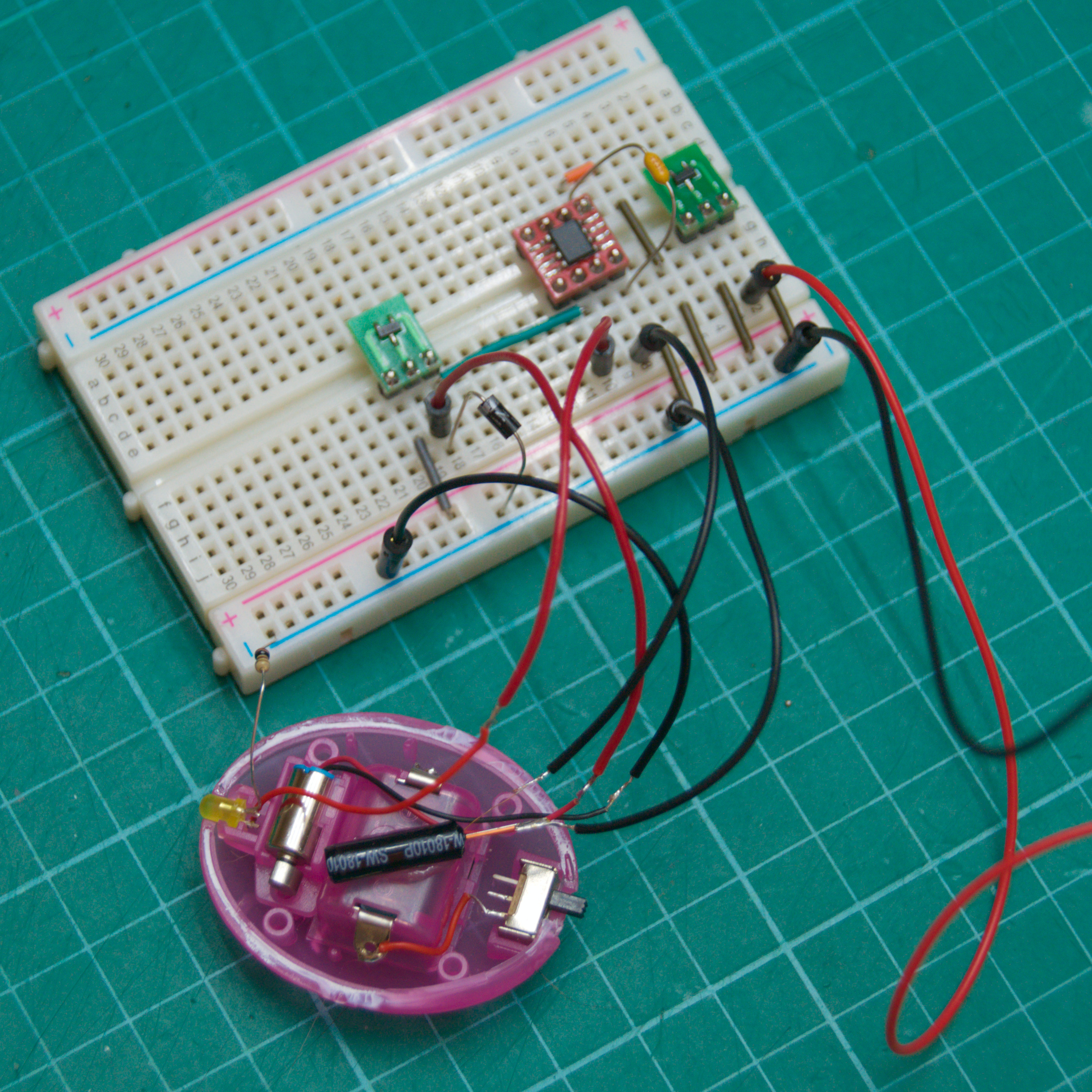
This way I was able to test the code as I wrote it. The code is below with a few notes following explaining some parts of the code. It is fully commented so that if in a few months I have a project I want to use the PFS154-S08 for I can look back at this project as a refresher.
/* Smart SmartyKat Crazy Cruiser
 * Target Device: PFS154-S08
 *
 * Sam Perry 2023
 * github.com/sdp8483/Smart_SmartyKat_Crazy_Cruiser
 */

#include <stdint.h>
#include <pdk/device.h>
#include "auto_sysclock.h"

// Pin Defines - all pins are on port A
#define VIBE_PIN              0     /* vibration sensor input pin, used to wake from deep sleep */
#define MOTOR_PIN             4     /* motor control pin, controlled with a pmosfet */
#define LED_PIN               3     /* LED output pin, current source */

// Output Pin Fuction Defines
#define LED_ON()              PA |= (1 << LED_PIN)
#define LED_OFF()             PA &= ~(1 << LED_PIN)
#define LED_TOGGLE()          PA ^= (1 << LED_PIN)
#define MOTOR_ON()            PA &= ~(1 << MOTOR_PIN)
#define MOTOR_OFF()           PA |= (1 << MOTOR_PIN)


// Toggle the motor on and off to give toy some character using profiles
#define MAX_TICKS             64    /* go to sleep after this many ticks */
uint8_t tick = 0;                  /* tick count, number of T16 interrupts since starting T16 */
#define NUM_PROFILES          8     /* number of profiles, a new one is played each wake event to give more character */
uint64_t profile[NUM_PROFILES] = {0b1100110011001111111111000000000010101010101010101010111111111111,
                                  0b1111111111111111111111111111111111111111111111111111111111111111,
                                  0b1100110011001100110011001100110011111111111111111111111111111111,
                                  0b1111111111001111001111001111001111001111001111001111001111001111,
                                  0b0101010101010101010101010101010101010101010101010101010101010101,
                                  0b1111001110011100111001110011100111001110011100111001110011100111,
                                  0b1110111000000111000000000000000011111111111111111111111111111111,
                                  0b1110101010101010000000001111111101010101000000001111111101010101};
                                   /* motor will be turned on when bit is 1 and off when bit is 0
                                       this playback profile is backwards */
uint8_t profile_i = 0;              /* profile number to playback, increments each wake */

// State Machine
typedef enum {
  GOTO_SLEEP,                       /* prepare to sleep */
  SLEEP,                            /* toy is in deep sleep */
  WAKEUP,                           /* toy was awaken from deep sleep */
  TOCK,                             /* T16 calling for next profile point */
  LIGHT_SLEEP,                      /* light sleep between ticks */
} fsm_states_t;

volatile fsm_states_t fsm_state = GOTO_SLEEP;

// Function Prototypes
void settling_delay(void);          /* use timer3 as delay to wait for vibe sensor to settle */

// Service Interrupt Requests
void interrupt(void) __interrupt(0) {
  /* Some notes and thoughts about interrupts on the PFS154
   *  Section 5.7 of the datasheet contains information about the interrupt controller.
   *  When an interrupt is triggered global interrupts are disabled, ie __disgint() is automatically called.
   *  CPU steps into ISR function below and executes code there. When done __engint() is automatically called and
   *  code execution starts in the main loop where it left off. Confusingly the datasheet says that even if INTEN = 0
   *  INTRQ can still be triggered by the interrupt source. So the peripheral or port should be further disabled to prevent
   *  triggering. */

  if (INTRQ & INTRQ_PA0) {          /* wake pin was pulled low */
    INTRQ &= ~INTRQ_PA0;            /* mark PA0 interrupt request serviced */
    fsm_state = WAKEUP;             /* change state */
  }

  if (INTRQ & INTRQ_T16) {          /* timer has expired */
    INTRQ &= ~INTRQ_T16;            /* mark T16 interrupt request serviced */
    T16C = 0;                       /* reset timer to zero */
    fsm_state = TOCK;               /* get next profile point */
  }

  if (INTRQ & INTRQ_TM2) {          /* LED toggle timer */
    INTRQ &= ~INTRQ_TM2;            /* mark interrupt request serviced */
    fsm_state = LIGHT_SLEEP;        /* go to light sleep */
  }

  if (INTRQ & INTRQ_TM3) {          /* settling delay has expired */
    INTRQ &= ~INTRQ_TM3;            /* mark interrupt request serviced */
  }
}

// Main program
void main() {
  MISC |= MISC_FAST_WAKEUP_ENABLE;  /* enable faster wakeup, 45 ILRC clocks instead of 3000 */

  // Initialize hardware
  PADIER = 0;                       /* on reset all pins are set as wake pins, setting register to 0 to disable */
  PBDIER = 0;                       /* there is no port B on the -S08 but without setting this to 0 the uC will wake unexpectedly */

  // Set Vibration Sensor pin as input
  PAC &= ~(1 << VIBE_PIN);          /* set as input (all pins are input by default, setting to make sure) */
  PAPH |= (1 << VIBE_PIN);          /* enable pullup resistor on pin */

  // Set output pins
  PAC |= (1 << MOTOR_PIN);          /* set motor control pin as output */
  PAC |= (1 << LED_PIN);            /* set led pin as output */
  LED_OFF();                        /* set initial LED state */
  MOTOR_OFF();                      /* set initial motor state */

  // Forever Loop
  while (1) {
    switch (fsm_state) {
      case GOTO_SLEEP:
        __disgint();                /* disable global interrupts */

        T16M = T16M_CLK_DISABLE;    /* turn off tick timer */
        TM2C = TM2C_CLK_DISABLE;    /* stop LED toggling */
        LED_OFF();
        MOTOR_OFF();

        settling_delay();           /* delay for vibe switch to settle */

        INTEN = 0;                  /* disable all interrupts */
        PADIER = (1 << VIBE_PIN);   /* enable only one wakeup pin */
        PBDIER = 0;                 /* make sure port B does not wake */
        INTEGS |= INTEGS_PA0_FALLING;
                                    /* trigger when switch closes and pulls pin to ground */
        INTEN |= INTEN_PA0;         /* enable interrupt on wake pin */
        INTRQ = 0;                  /* reset interrupts */

        fsm_state = SLEEP;          /* change state */
        break;

      case SLEEP:
        __engint();                 /* enable global interrupts */
        __stopsys();                /* go to deep sleep */
        break;

      case WAKEUP:
        __disgint();                /* disable global interrupts */
        INTEN = 0;                  /* disable all interrupts */
        PADIER = 0;                 /* disable wakeup pin */
        PBDIER = 0;                 /* disable port B wake pins to be sure */

        T16M = (uint8_t)(T16M_CLK_ILRC | T16M_CLK_DIV1 | T16M_INTSRC_13BIT);
                                    /* use 55kHz clock divided by 1, trigger when bit N goes from 0 to 1
                                     * T16 is used as the tick count to determins playback of profile for motor */
        T16C = 0;                   /* set timer count to 0 */
        INTEN |= INTEN_T16;         /* enable T16 interrupt */
        INTRQ = 0;                  /* reset interrupts */

        // use timer2 to toggle LED
        TM2C = (uint8_t)(TM2C_CLK_ILRC | TM2C_OUT_PA3 | TM2C_MODE_PERIOD);
        TM2S = (uint8_t)(TM2S_PRESCALE_DIV4 | TM2S_SCALE_DIV3);
        TM2B = 250;                 /* set timer frequency to 6.8Hz */
        INTEN |= INTEN_TM2;         /* enable timer2 interrupt */

        tick = 0;                   /* reset tick count to reset profile playback */
        fsm_state = TOCK;           /* change state to set motor playback from profile */
        break;

      case TOCK:
        __disgint();                /* dont interrupt during tock */
        if (tick >= MAX_TICKS) {    /* done playing? time for sleep */
          profile_i++;              /* play next profile on wake */
          profile_i = (profile_i > (NUM_PROFILES - 1)) ? 0 : profile_i;
                                    /* constrain profile_i */
          fsm_state = GOTO_SLEEP;   /* change state, go to sleep */
          break;                    /* don't execute remainder of code */
        }

        // get motor state in profile playback based on tick number
        if (((profile[profile_i] >> tick) & 0b01) == 1) {
          MOTOR_ON();
        } else {
          MOTOR_OFF();
        }

        tick++;                     /* increment tick */

        __engint();                 /* enable global interrupts */
        __stopexe();                /* light sleep, ILRC remains on */
        break;

      case LIGHT_SLEEP:
        __engint();                 /* enable global interrupts */
        __stopexe();                /* light sleep, ILRC remains on */
        break;

      default:
        fsm_state = GOTO_SLEEP;     /* something is wrong, go to sleep */
        break;
    }
  }
}
// Use timer3 to delay while vibration sensor settles
void settling_delay(void) {
  TM3C = (uint8_t)(TM3C_CLK_ILRC | TM3C_OUT_DISABLE | TM3C_MODE_PERIOD);
  TM3S = (uint8_t)(TM3S_PWM_RES_8BIT | TM3S_PRESCALE_DIV4 | TM3S_SCALE_DIV13);
                              /* setup for 0.256sec period */
  TM3B = 250;                 /* timer3 counts up to this value before interrupting */
  INTEN |= INTEN_TM3;         /* enable interrupt for timer3 */
  __engint();                 /* enable global interrupts */
  LED_ON();                   /* to see that delay is happening */
  __stopexe();                /* light sleep for a delay */
  LED_OFF();                  /* delay is done */

  __disgint();                /* disable global interrupts */
  TM3C = TM3C_CLK_DISABLE;    /* disable timer */
}

// Startup code - Setup/calibrate system clock
unsigned char _sdcc_external_startup(void) {
  /* Set the system clock
   * note it is necessary to enable IHRC clock while updating clock settings or CPU will hang  */
  PDK_USE_ILRC_SYSCLOCK();          /* use ILRC 55kHz clock as sysclock */
  PDK_DISABLE_IHRC();               /* disable IHRC to save power */
  EASY_PDK_CALIBRATE_ILRC(F_CPU, TARGET_VDD_MV);

  return 0;   // Return 0 to inform SDCC to continue with normal initialization.
}
Here are some of the highlights of the code and why I went in the direction I did.
- The main code loop contains a state machine. This was the simplest way for me to organize the code and to have the toy go though a few different modes.
- During play time the code is executed using Timer16 to generate an interrupting clock that I call tick.
- The motor is controlled using on/off commands. I thought using PWM to control the motor was more complicated then needed. Instead the profile variable stores a 64bit variable that is shifted through bit by bit to set the motor state for each Timer16 interrupt. When the code is finished shifting through this variable then the toy goes to sleep.
- The profile variable is an array so that the toy does not behave the same way each time it wakes. This gives it some character and hopefully makes it more fun.
- The LED is blinked using Timer2. I was toggling it using the TOCK state but that meant that the toggle rate was linked to the tick rate. I wanted the LED to toggle faster then I wanted tick to run. I found that Timer2 regardless of if the INTEN bit for it was set would call the interrupt function and mess with how long it took the toy to shift through the profile. To solve this when Timer2 interrupts it sets the state the LIGHT_SLEEP. This way the TOCK state is only called after an interrupt from Timer16.
- I used Timer3 as a settling delay. I thought that if the vibration switch was still wiggling while the toy was getting ready to sleep then the toy would never sleep. This way there is a ~256ms delay to let the motor spin down and the vibration switch to settle down.
That is it for the code. I have achieved my goal so far with the modification. The toy is easy to wake up with a slight tap and then remains active for about 10 seconds. If the toy is still being played with it continues running for longer but otherwise it goes into deep sleep to save battery power. In deep sleep I measured a current consumption of 0.3uA at 3.0V. During play with the same voltage I measured a maximum of 40mA.
Now for the final part of this project, get everything back in the housing and button it up. It looks like it will be tight so I may have to cut away some of the internal supports to make room.
Final Assembly
I was able with a little coaxing to stuff all the electronics back into the toy and reassemble it. With some help from my lab assistant in the photo below, assembly took about 1.5 hours.

I started assembly by placing the vibration switch first since it was the largest of the new components. I trimmed some of the plastic supports and glued it into place on the side under the negative battery terminal. Then I soldered the input protection MOSFET to the power switch utilizing the unused 3rd pin on the switch to make a positive power rail. The PFS154-S08 was glued to the top of the battery compartment. The final component to place was the MOSFET for the motor which I also soldered to the 3rd pin on the power switch.
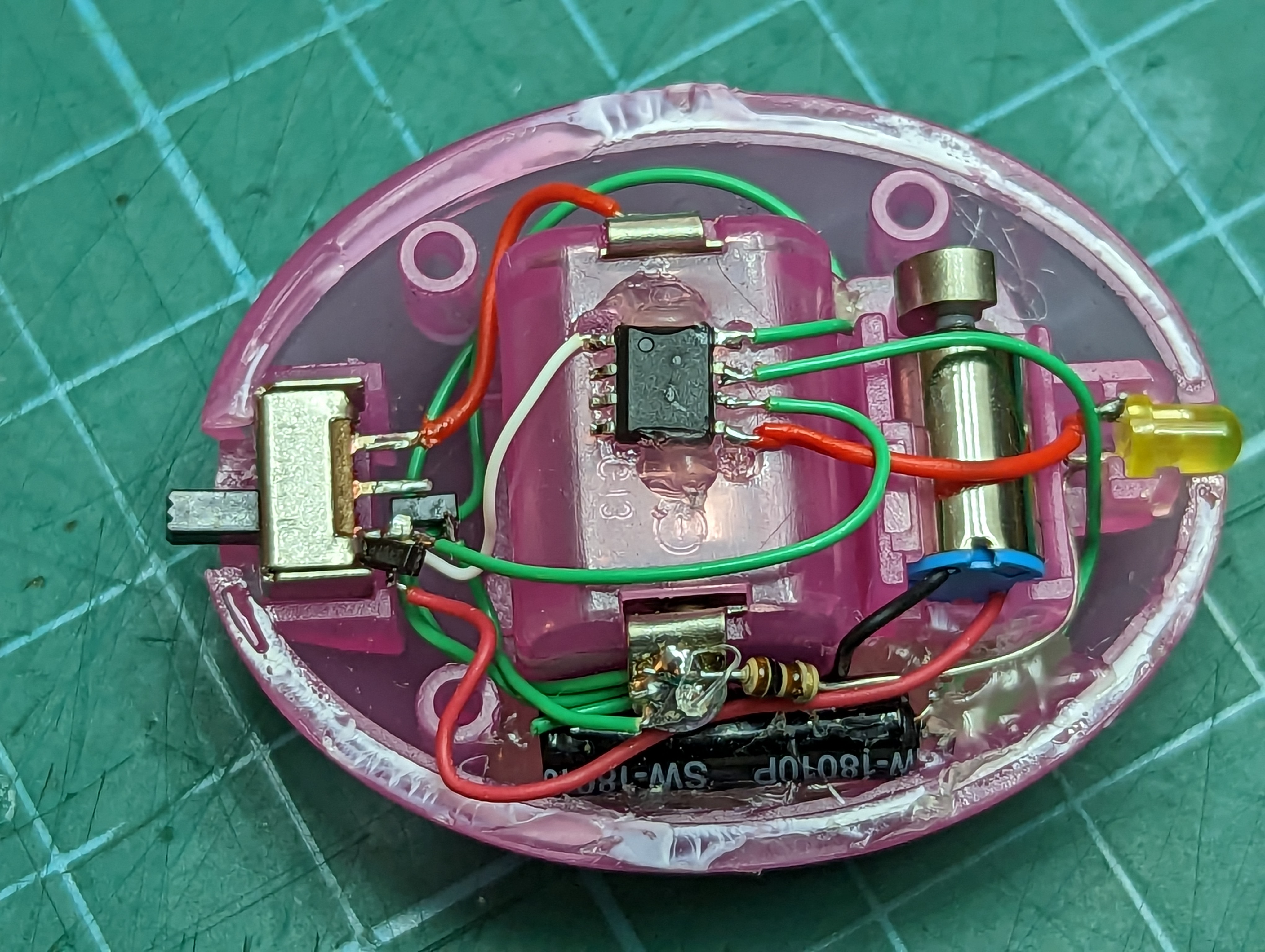
With everything wired up I tested the toy to make sure it would work and then filled in some of the areas with hot glue to reduce the chance of connections working loose.

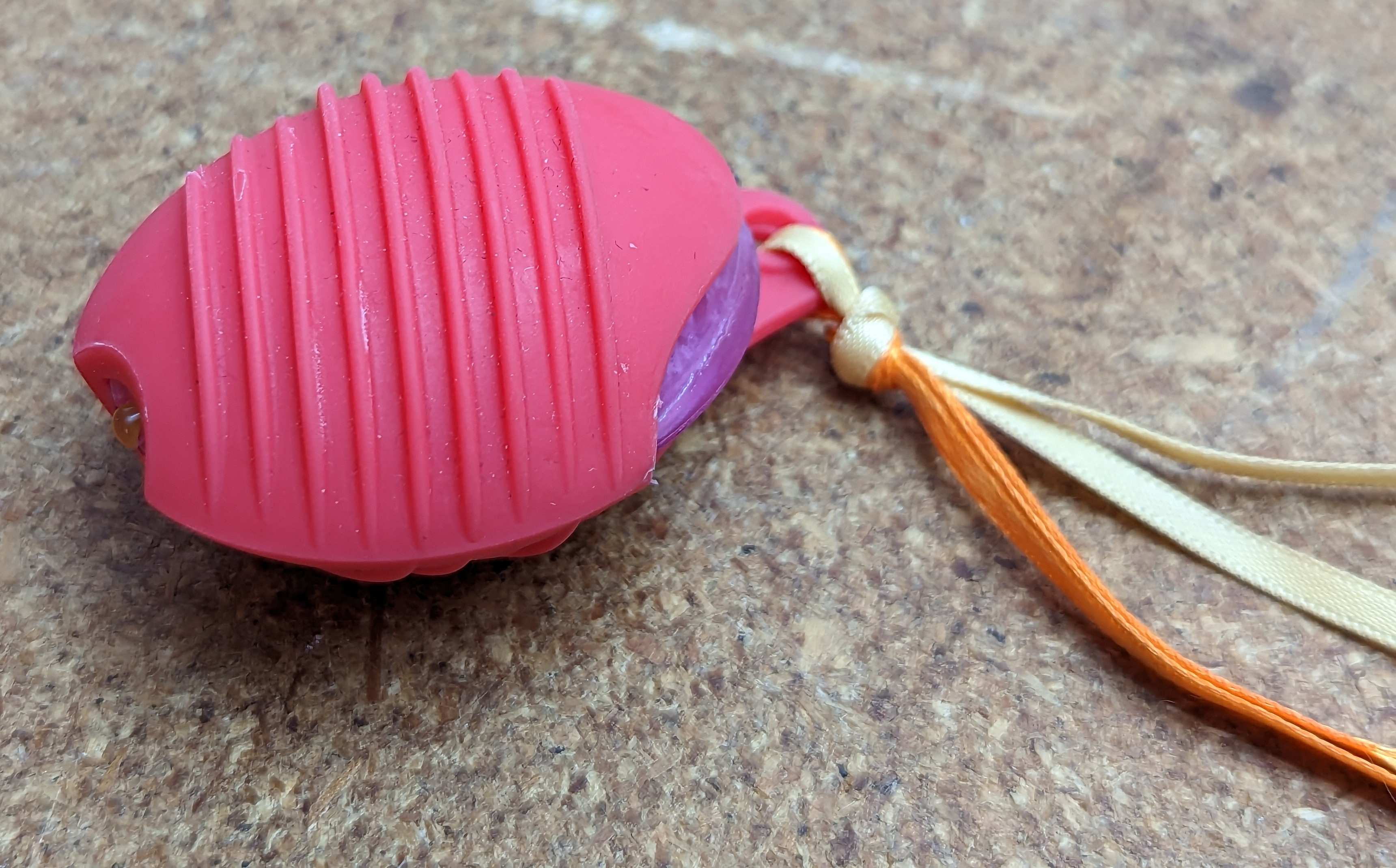
The final step was to test fit the cover and then after confirming everything would fit I applied super glue to the seam to seal up the electronics.
Now for some play testing and obligatory cat video.

🤣🤣🤣🤣
I was hoping we had a shot of the “lab” assistant!
What a very spoiled cat!!
Loved reading all the steps taken to insure smart playtime.
LikeLike