
After selling out of both of the Multi-LED Joule Thief and the Joule Thief Candle on Tindie it became necessary to not only make more but to update both models. Before updating I wanted to make a few measurements of the circuit to better understand how I could increase its performance by changing the resistance of R1 connected to the base of the NPN transistor in the schematic below.

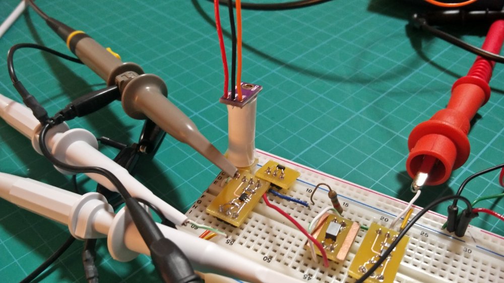
Using breakout boards for the SMD components I built up a breadboard version of the Joule Thief Candle to experiment with a few different components. The break out boards along with more information is available in the following github repository.
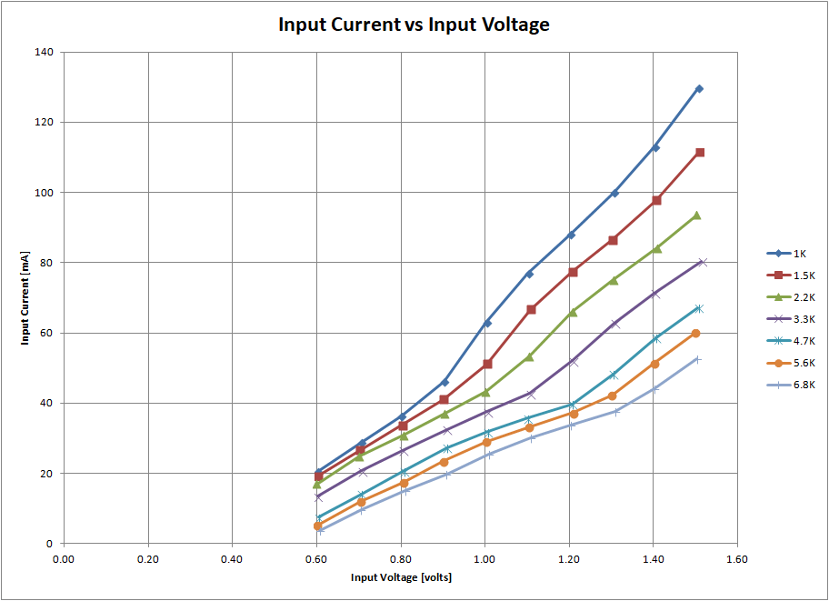
For the Joule Thief Candle and the Multi-LED Joule Thief I had arbitrarily picked a resistance of 1K but I wanted to see what the effect would be of increasing that resistance. I chose to test the following values of R1 based on the resistors I had available; 1K, 1.5K, 2.2K, 3.3K, 4.7K, 5.6K, and 6.8K. I measured not only the current consumption of the total circuit but also the input voltage, LED current, LED light level, and switching frequency of the LED. I also measured the turn off voltage and turn on voltage of the circuit. The results are all available in the following Excel file.
The resistance of R1 is inversely proportional to the input current at a given voltage. I want to target a low input current to increase battery life for the next Joule Thief version but at the same time not sacrifice LED brightness.
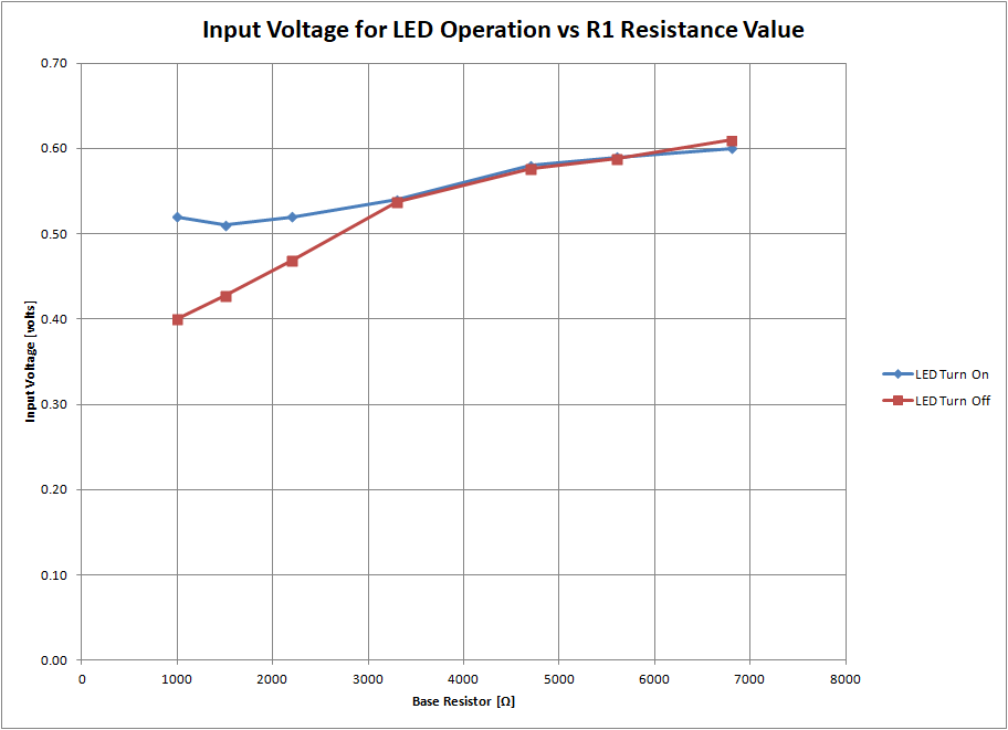
The resistance of R1 changes the turn on and turn off voltage of the circuit slightly. The amount of energy in a AA cell at 0.6V compared to the same cell at 0.5V is insignificant and as such the results of this testing while interesting will not have a great impact on the final value of R1 in the new designs.
Current through the LED is proportional to brightness. The higher the current the higher the brightness but at a cost of battery life. The plot below shows that increasing the resistance of R1 causes the current passing through the LED to increase at a given input power. So for example at 75mW of input power the LED current is about 12mA with R1 = 1K and is 15mA with R1 = 6.8K. The efficiency of the circuit improves with increased resistance of R1, that is to say more of the input power goes to the LED.

Based on the following charts I chose to change the value of R1 from the original 1K to 6.8K. This new resistance value will be used in the updated versions of the Joule Thief Candle and the Multi-LED Joule Thief.
All the information presented above is available in a github repository including KiCAD files for the breakout boards, a BOM list of components used, and the data collected during testing. Also be sure to check out my previous posts of the Multi-LED Joule Thief and the Joule Thief Candle and their github repositories available here and here respectively.
View other related Joule Thief articles.


2 thoughts on “Joule Thief Measurements: Base Resistor”