The Problem
During short instances of nice weather in upstate New York I enjoy going for a bicycle ride on the local multi use trails. I have to pass pedestrians or slower bicycle traffic and find it to sometimes be a hassle to get their attention. During one of my rides I got to thinking about this problem and was hoping for a solution as easy as pushing a button, enter the bicycle announcer (needs a better name). In this post I will outline the solution I have developed for this problem so that I can get back to enjoying the summer weather.
The Solution
A go-to quick solution may have been to get a bell but I did not want a simple bell and also I needed an excuse to make something. My solution is to push a button that will play a sound file indicating the passing direction, ideally the left but sometime traffic is not on the right so I want both options. I believe this would be possible with an Arduino but I wanted better quality audio and an excuse to use the Teensy 3.1 I purchased long ago with an OSHPark PCB order. I watched this video a few weeks before starting this project and was amazed at the ability of the Teensy to produce sound so that initially helped influence my microcontroller choice. I dug through my junk bins for supporting components and then ordered the rest.
The Components
As stated above I already had a Teensy 3.1. To produce audio I purchased the Teensy Audio Board which includes a microSD card slot, I will store the audio files on a medium capacity microSD card. The output from the audio board is not able to drive a speaker so I picked up the PAM8302A Mono Audio Amplifier to drive a 4-8Ω speaker. For the speaker I dug into my junk bins and found a 8Ω 0.5W speaker of unknown origin. I only have one but mono sound should be more than good enough for this project.

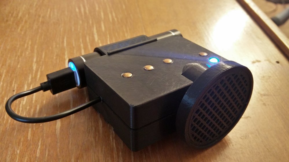
Instead of mechanical buttons as user input I wanted to experiment with the capacitive touch functionality of the Teensy 3.1. For the touch buttons I used small copper rivets that I had in my fastener bin, not sure where they came from but they seem to work well.

The final component for this project is the power supply. This project needs to be battery powered and have a medium to long battery life of hours. Preferably the battery should be rechargeable. The Teensy is powered from 3.7 to 5.5V. Not wanting to mess around with building a battery circuit I looked for the cheapest USB power bank I could get from Amazon in the small lipstick sized form factor. This power bank outputs 5V at 1A maximum and claims 2600mAh capacity but testing reveals the capacity is closer to 1300mAh.
The Circuit
The circuit in the schematic below was built up on a breadboard for initial testing and code debugging.

A few things of note about the schematic.
- The Teensy 3.1 and the audio board are stacked on top of each other just like they were designed to be. I drew them separately on the schematic so that I could see the pins that the audio board was using on the Teensy.
- The power bank has an auto off feature, when the current drops below ~75 mA the voltage output shuts off. I briefly looked into modify the power bank to disable that feature but ultimately I went for simplicity at the expense of a higher idle current. The 100Ω resistor and green LED push the idle current of the entire circuit to around 88 mA.
- The Teensy website mentions adding 1K or high resistors on all touch pins to prevent electro-static shock when not placing the touch pads under an insulating layer. This is for the AVR versions of the Teensy which do not have built in capacitive sensing hardware. Looking through the datasheet quickly for the microcontroller on the Teensy 3.1 I did not see mention that this protection was built in so to be safe I have added the resistors. The resistors do not seem to reduce sensitivity.
The Code
Rarely can I write code from scratch and often build off of examples or previously written code, this project was no exception. I started with the WaveFilePlayer example for the Teensy. I will walk through some of the key features I added. The code presented below is for illustration purposes only and is not presented in its entirety, if you wish to copy any part or all please download the complete code available which is available on github.
The WaveFilePlayer example is installed with Teensyduino. It is located in File->Examples->Audio->WaveFilePlayer. I built upon this code to play my wav files, the code will play the filename passed to the playFile() function. The files must be located in the root directory of the microSD card. Not wanting to hear my voice I found the following two recordings; “On the Left” and “On the Right“ from Project Shtooka. These files were free to download and were exactly the phrases I was looking for.
In addition to playing audio files I wanted a simple tone to play before each file. So I played around with adding two sine waves of different frequencies together until I got something I liked. A few other examples and the Teensy Audio System Design Tool gave me the code to play two sine waves followed by an audio file.

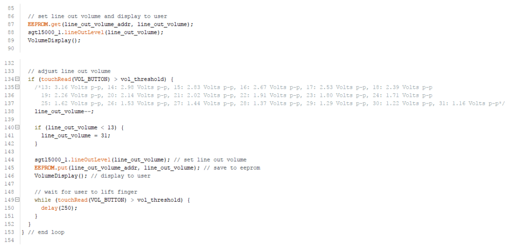
Reading touch sensors with the Teensy is as easy as calling touchRead(n). This function returns an integer read from pin n. When the pin is touched the returned integer value increases. I wrote a function, AdjustTouchThreshold(), that reads each capacitive touch pin on startup to determine the untouched value. The pin is then considered touched when touchRead(n) returns a value THRESHOLD_TRIGGER counts larger than its initial value. I found during testing that since this project is not earth grounded this THRESHOLD_TRIGGER has to be a low value so that the touch inputs are sensitive. This is only true when running off of battery power, if the Teensy is powered through the USB port for debug or code change this threshold can be too sensitive and cause false triggers. I have yet to see if I will need to make adjustments when it is installed on my bicycle.

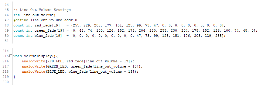
The PAM8302A module has a tiny volume adjustment potentiometer but this would be inconvenient to adjust while riding. I set the potentiometer to output max volume and instead use software to adjust the line out level from the audio board to the amplifier. The volume for the line out is set by calling sgtl5000_1.lineOutLevel(n) where n is an integer from 13 to 31, a value of 13 is the loudest. The volume touch button decrements the line out level by one until dropping below 13 where it will be set to 31. The volume level is saved to EEPROM so that on power off the last volume setting is retained.
As an easy indicator of the volume level I decided to fade an RGB LED. Blue indicates a low level, green is for a medium level, and red indicates a high level. The LED fades between two colors to indicate any level in between. This lets me know what the volume is without having to add a display.
The remainder of the code was generated from the examples I followed or is pin definitions and global variables, really boring stuff. Again all the code is available on github and should be the source you use if you wish to copy the code.
The Final PCB

With my schematic in hand and a working prototype on breadboard I set to making this project more permanent by mounting it to a PCB. Trying to keep the final circuit as small as possible I mounted everything to a 30mm x 70mm prototype PCB. Before starting to solder I laid out the board and components using graphing paper, it is easier to erase a pencil line from paper when something is not laid out right then to desolder. This graph paper layout worked great for getting the component spacing correct. I added headers for the RGB LED and the touch buttons that will be mounted remotely from the PCB. To connect the line out from the audio board to the audio amplifier I used a short piece of ribbon cable soldered directly to the pads on the audio board. In an effort to reduce the height of the final PCB I did not add female headers for the Teensy and instead soldered it directly to the main PCB. All connections were wired with small gauge scraps of wire and ribbon cable. Where possible I used SMD resistors but did not have 330Ω surface mount resistors so I cut the leads short on the smallest through hole resistors I had to make them surface mount.


The Measurements

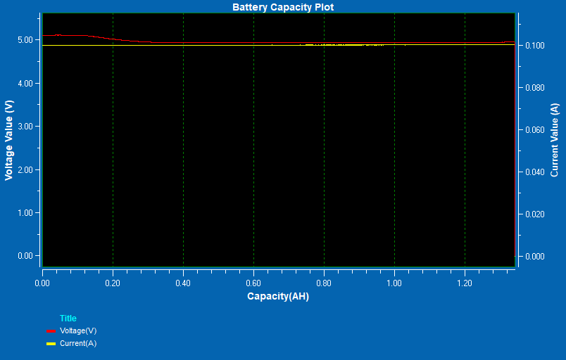
Before moving on to designing the case I wanted to take a few measurements of the assembled circuit for power consumption to make sure that the power bank I planned to use would be able to provide a long enough battery life for my typical 40-80 minute bike ride. For data logging I have a DI-1110 USB datalogger. I installed a high side current shunt using the MAX471 on channel one and then connected the battery voltage to channel two. I also monitored the amplifier shutdown pin and the speaker voltage using the datalogger. I recorded these four signals while both audio files were played at the highest volume level. The maximum sample rate of the DI-1110 is 160 kHz which is divided by the the number of acquired channels, so each channel was sampled at 40kHz. The plots presented below have been compressed by 230 to reduce the amount of points that matplotlib has to draw.
I found that the idle current over a 10 second recording was on average 88 mA with minimum and maximum peaks of 73 mA and 100 mA. Assuming a worst case constant idle current of 100mA the battery life should be about 1300 mAh / 100 mA = 13 hours, long enough for a few days of riding.

Of course when not at idle the power consumption will be significantly higher and will decrease that 13 hour estimate. The plots below show the current and voltage while playing both the wav files. The average current when playing each file was about 193 mA. Both files play for 1.94 seconds from when the amplifier is enable to when the amplifier is disabled. To make the calculations easier let’s assume that the files are constantly playing and that the current is 200mA, our battery life calculation would then be 1300mAh / 200 mA = 6.5 hours. This situation would never happen but even if it did that is a significantly long battery life for one day of riding.


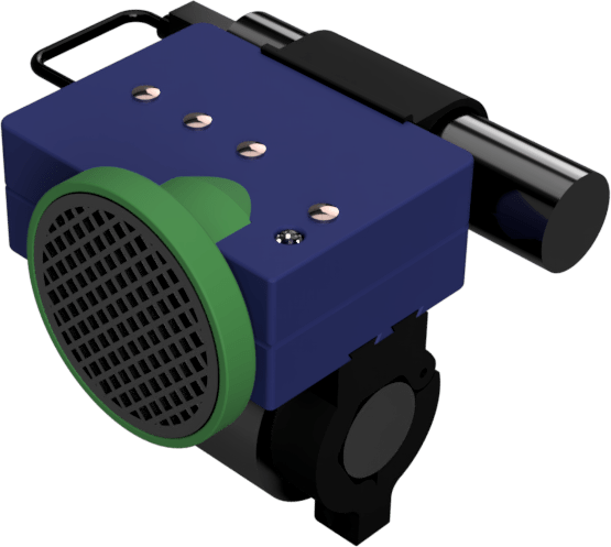
The Case
I needed a case to contain this project that could attach to my bike while also allowing me access to the touch buttons. When designing a case I always start with modeling what will be contained inside. It does not need to be in full detail, just the rough shapes. Then from there I can arrange the major components around a simple model of the bicycle handle bar and build the case around the components. The overall design changed a few times due to size and mounting location. I had originally hoped to mount the case in such a way that it could be activated using my thumb while still holding onto the handle bars. The bicycle does not have enough room to mount the case close enough to one of the handle grips given the size of my final PCB and speaker. I would have to abandon triggering it with my thumbs and mount it elsewhere.
In the end I happened to watch a video from The Ben Heck Show where they too were designing something to mount on a bicycle and mounted it in the center of the handle bars straddling the fork. Not being ashamed to copy an ideal I decided to mount my project there and also borrowed the design of the mounting clamps from that episode.


I made extensive use of dovetails to enable the case to be removed from the mounting clamps and to also allow the battery to be removable from the case. I wanted to be able to remove the case since I leave my bicycle in the back of my car and do not want to leave a lithium battery inside a hot car. I was also concerned that the 3D printed case would melt in the high heat of a car during the summer since I print mostly using PLA. I have since left the clamps attached to the bicycle inside the car and have not had any issues with heat damaging them. Still better to be safe and melt some easy to reprint clamps then a full case.
With the case designed I spent a day 3D printing everything and then a few hours were spent assembling everything into the case. There was one small modification that I needed to make before I could mount the PCB into the case. I forgot to model the 3.5mm jack on the audio adapter board and it just so happened to interfere with one of the pillars from the top of the case so it was removed and everything went together nicely from there.
The First Ride
I attached the announcer to my bicycle using the clamps with a small cutoff of inner tube to prevent the clamps from slipping on the handle bars. I then set off for the first ride using this project and learned the following list of items.
The alert tone is too loud. I lowered its volume by changing the amplitude of both sine waves from 0.6 to about 0.3- The alert tone playing before the WAV files is annoying, I have disabled that feature and will use the tone button if it becomes necessary to play a tone.
- The micro USB is somewhat accessible after removing the top of the case and loosening most of the pcb screws. Any future redesigns should ensure it is 100% accessible with the top cover off.
- To trigger the touch buttons I had to also be touching the battery case. I lowered the touch threshold and now am able to trigger the buttons without having to touch the battery case.
- The battery holder was loose fitting and bounced around while riding. I reduced the clearance of the dovetail connecting it to the case to a 0.15mm gap from 0.2mm. A reprint later and it is now nice and tight.
- The mounting clamps hold up to ridding and allow the unit to be removed after use. It is a little tricky removing the unit requiring one clamp being removed first and then twisting the unit to remove the other. Mounting the unit a little higher from the handlebars should enable removal to be easier. I may at a later date redesign this but only if something breaks or it becomes too annoying to use.
The Conclusion
In the end I was able to design something close to what I had originally wanted. A smaller PCB footprint and smaller components overall would enable it to be mounted as originally planned but would require more design work and a custom PCB, maybe in a future revision. For now I am going to get outside and enjoy the remainder of the summer.
All design files including schematics and code is available on github for use and modification: https://github.com/sdp8483/bike_announcer

Just spent some time reading over this, how clever and now no crabby pedestrian can yell at you for sneaking up on him with you bike, I do wonder what the sound is, a video would be really nice😊, good job Sam have fun riding! Mom
LikeLike