After replacing the electrolytic capacitors and linear voltage regulators in my Keithley 177 multimeter I left the unit running for an extended period of time to make sure no other issues appeared. Less than 12 hours later the main fuse had blown. I traced the issue down to the transformer which was generating excessive amounts of heat. To make sure that there was not a short elsewhere in the meter I removed the transformer and found that with no load the transformer still overheats, time to replace the transformer. After having no luck finding an exact replacement I set about designing a whole new power supply for the Keithley 177.

Finding a suitable transform to replace the original was not a simple task. Off the shelf transformers where either much larger than the original or would not provide the same power output. For a few dollars more than a traditional transformer and a whole lot less hassle I went with a AC/DC converter module. The RAC20-15DK from RECOM Power is an all in one AC to DC converter that also offers regulated ±15V rails with 100mVp-p ripple, eliminating the need for the linear regulators in the original Keithley 177 power supply. This module is able to supply 20W, the Keithly draws a maximum of 8W according to the manual. I integrated this power module into the 177 in such as way so that the original 1/8A AC mains fuse will still be protecting the meter and preventing the meter from ever drawing the full 20W of the power module.
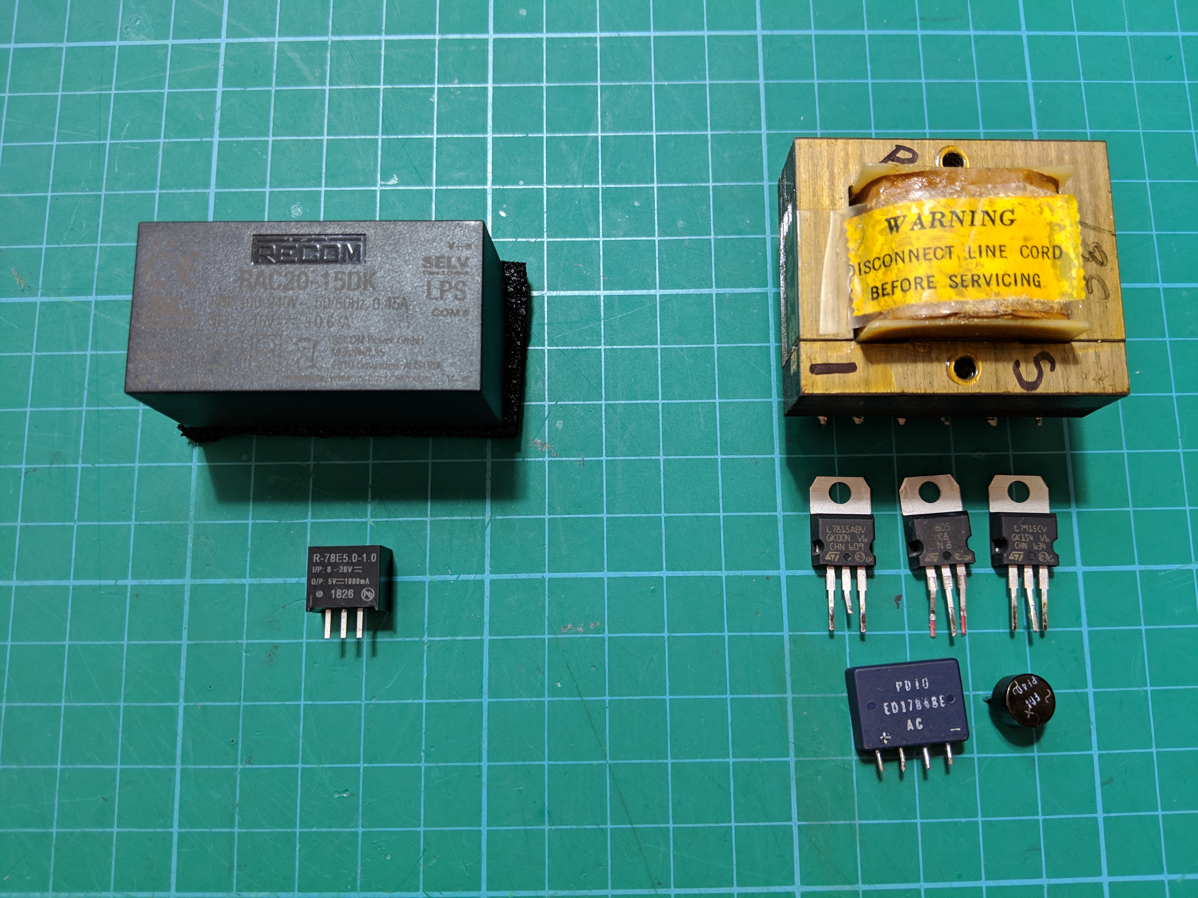
Since I was replacing the ±15V linear regulators I decided to also replace the 5V linear regulator with a DC/DC converter module also from RECOM, the R-78E5.0-1.0. This is a 5W module with 120mVp-p output ripple. The 5V rail is used to power the digital section of the Keithley 177 so I am less concerned about output ripple and noise.
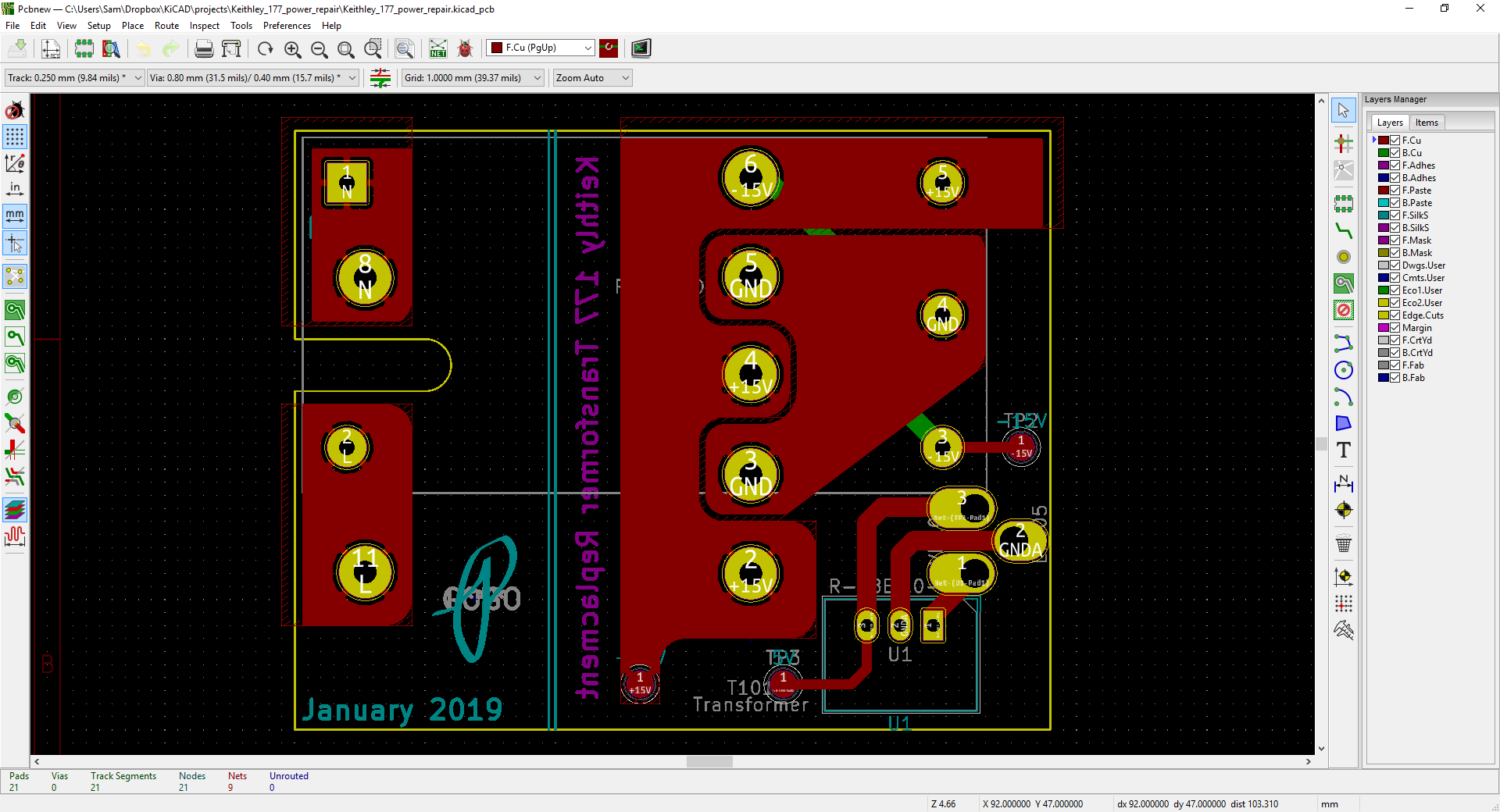
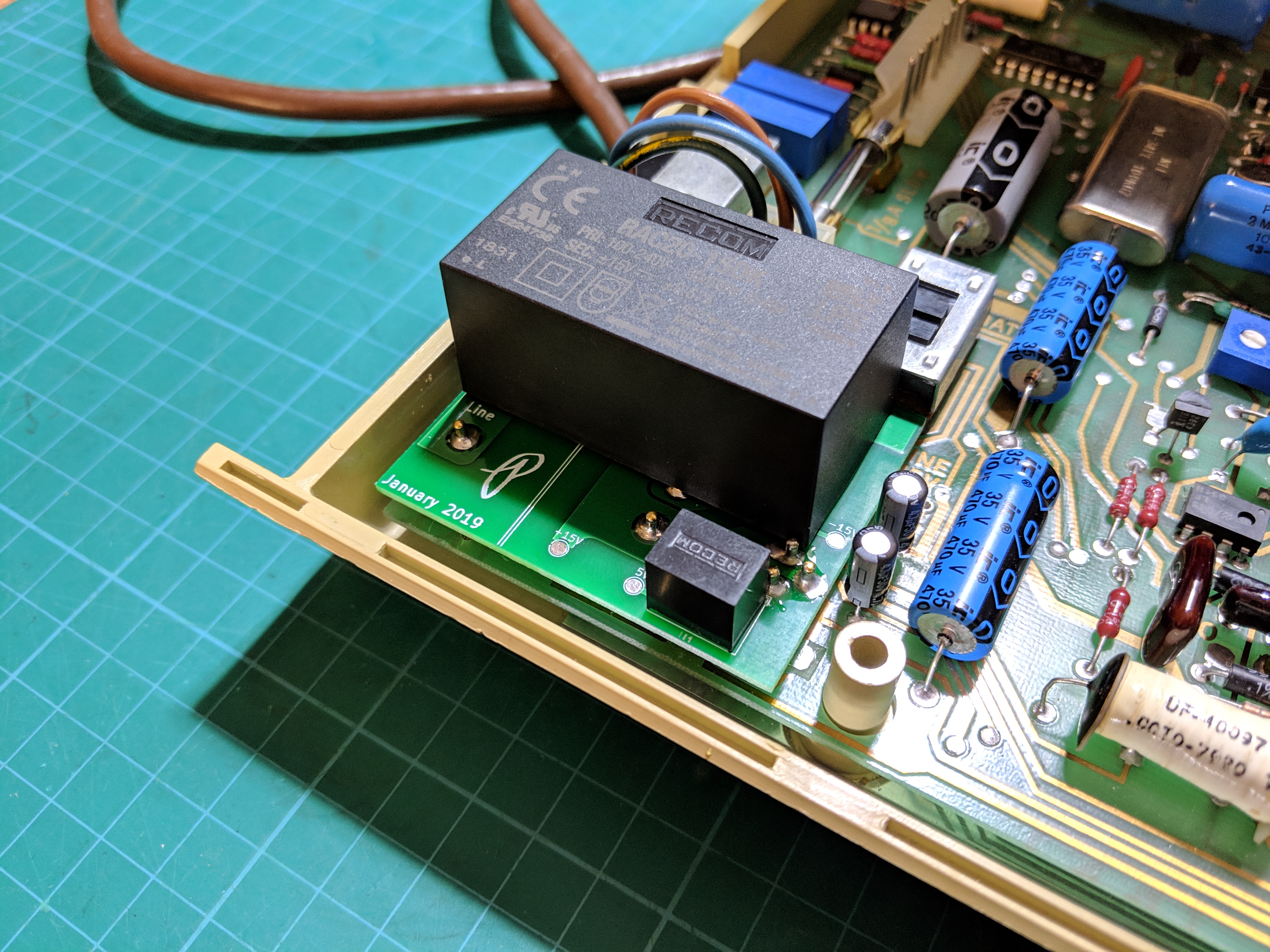
To integrate these new power modules into the existing Keithley PCB I designed an adapter PCB that makes use of existing footprints on the main PCB. These two PCBs are then connected using single pin terminal posts, part number 6035-0-00-15-00-00-03-0 from Mill-Max Manufacturing. I chose these pins over using solid core wire since they have a shoulder on them that will act as spacers between the two PCBs and make soldering much easier. Plus they look cool and are reasonably priced.

In designing the adapter PCB it was necessary to make measurements of the main PCB and footprints. I started off making measurements with calipers but in the end I found it useful to take a high resolution scan of the PCB and then use a program called BigPrint to scale the image and take the measurements. This software was created by one of my favorite YouTubers, Matthias Wandel. He offers an eval copy of the software that is perfect for making PCB measurements, I purchased a copy since I found it so useful and wanted to support more such projects.

Preparing the Keithley 177

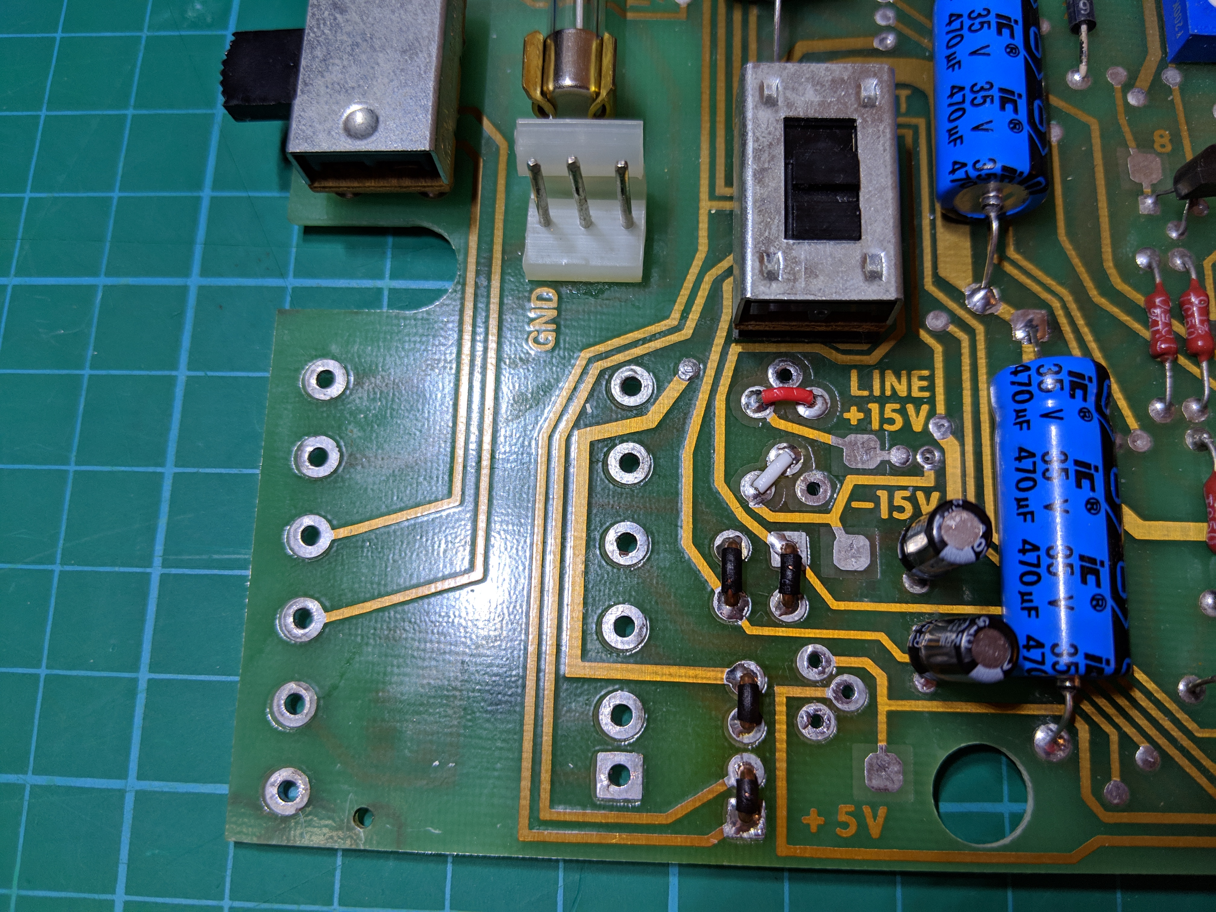
With adapter PCB and power modules in hand it was time to start modifying the main PCB to accept the new power supply. The following components were removed:
- AC Transformer T101
- Bridge Rectifier CR103 and CR104
- 5V Linear Regulator VR101
- +15V Linear Regulator VR102
- -15V Linear Regulator VR103
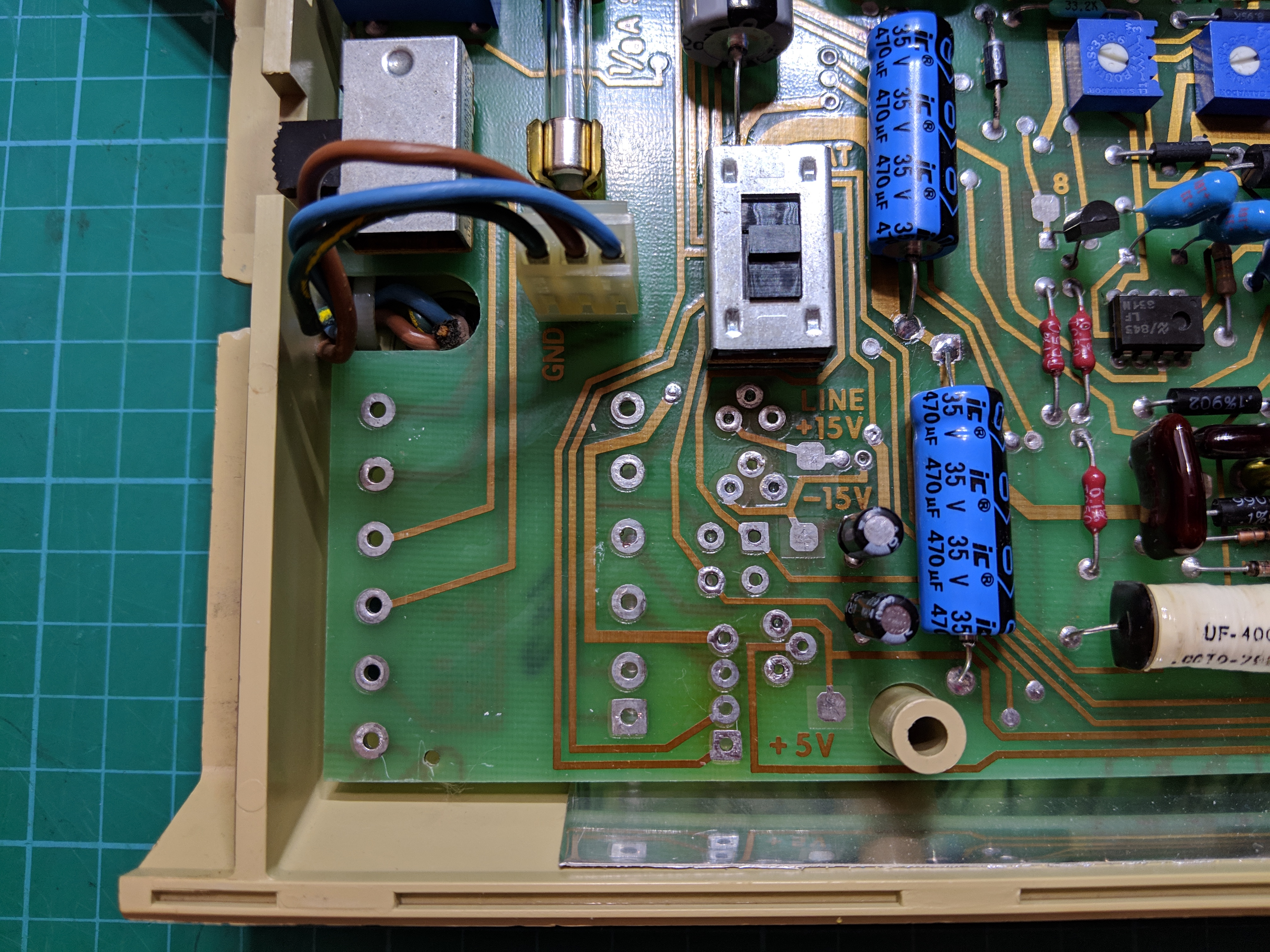
Before soldering in the adapter PCB the following links were made on the main PCB using small sections of wire. The photo below and modified power schematic do a better job of describing the placement of the links then I could ever do with words.

Installing New Power Supply
To install the adapter PCB I first placed the terminal pins in the proper positions on the main PCB. I did not solder them to the main PCB yet since this step is only for aligning them to the adapter PCB during soldering. Unfortunately the diameter of these pins were too big for the 5V regulator footprint on the main board. I was able to turn the pins down using a cordless drill and jewelers file until they fit the holes since I did not want to modify the Keithley PCB anymore then I already have.
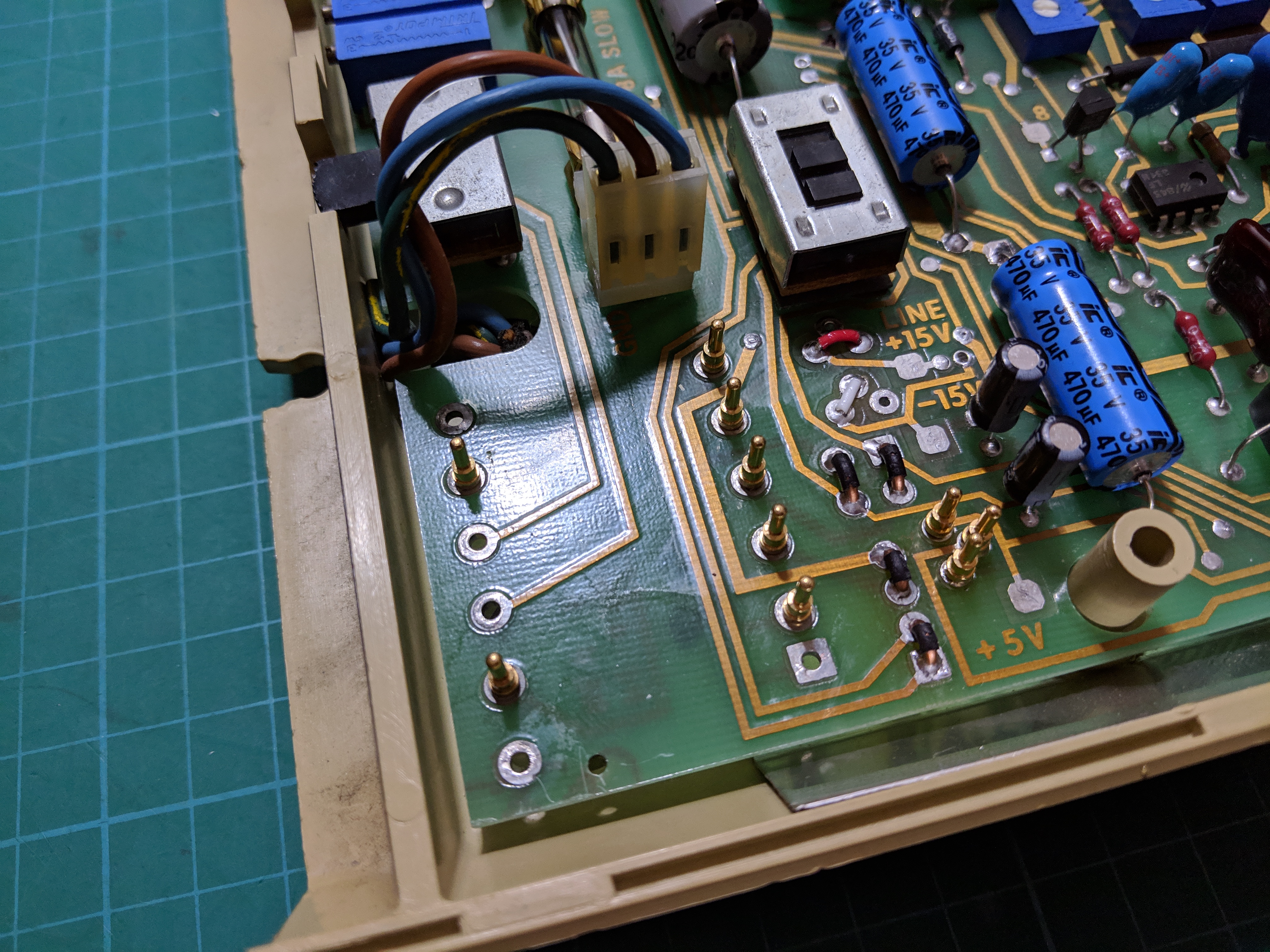
With all the pins in the main board I then placed the adapter PCB onto the pins and soldered in place. This makes aligning the pins super easy and corrects any errors in the pin spacing.
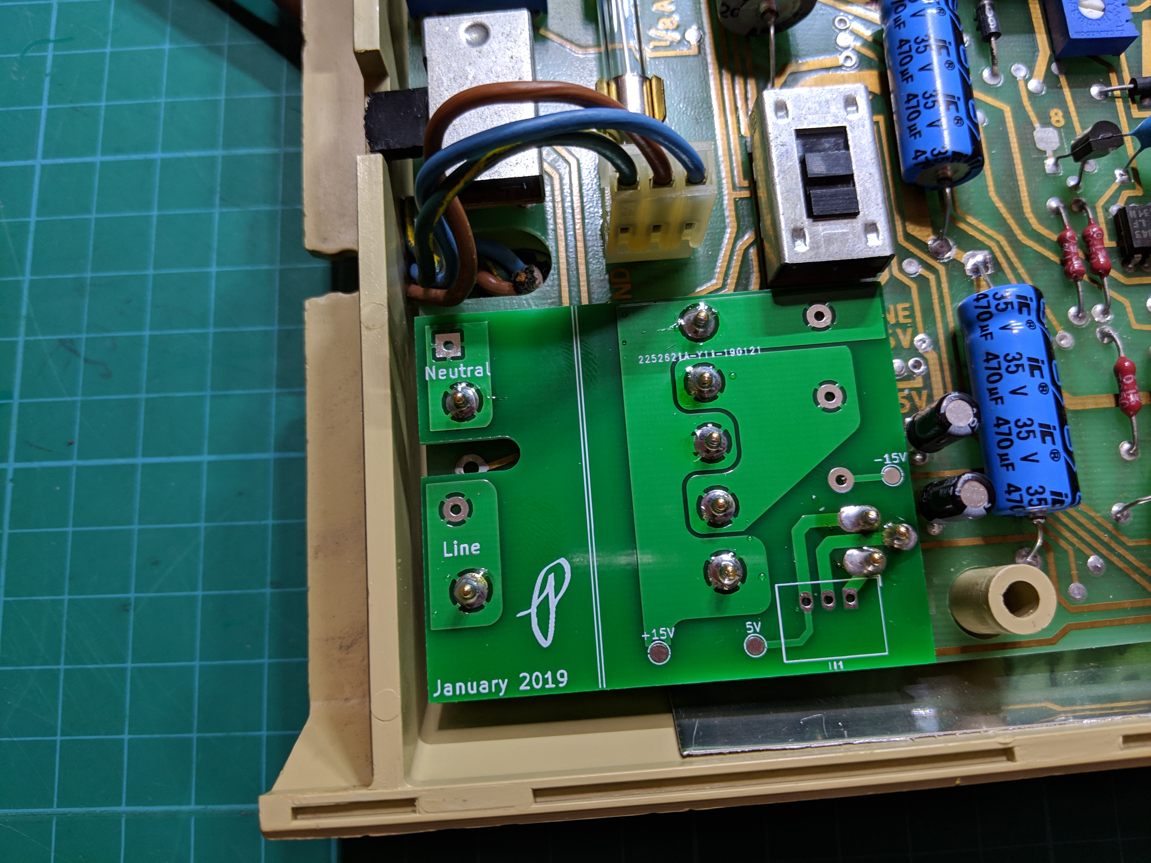
With the pins soldered to the adapter PCB I then trimmed down the top side of the pins that are directly under the RECOM AC/DC power module so that this component would sit closer to the PCB.

With that done I soldered both RECOM power modules to the board. Now the adapter can be installed into the main PCB and soldered in place.
I then crossed my fingers and slowly plugged the power cord into the outlet, just in case I made a big mistake. Then I made a quick sacrifice to the electronic gods and hit the power button. It worked as I knew it would, there was never a doubt in my mind. My Keithley 177 multimeter is now fully repaired and ready for calibration and use.

Some Notes and Warnings
If you’re in need of replacing the power supply on your Keithley 177 I would like to point out a few things before you follow my approach. First, make sure you are comfortable working with line voltage and stay mindful of live circuitry when probing around. I didn’t use one but it would be smart to use an isolation transformer whenever working on AC powered instruments. It’s on my list of equipment to get soon.
The RECOM REC20-15DK is a universal AC input module that can accept voltages from 85 to 264VAC so the voltage input selection switch on the instrument is no longer needed. I connected my adapter PCB in such a way that it will function correctly regardless of the switch position.
Since the RECOM REC20-15DK module offers greater output power then the instrument’s requirements, I made sure my design does not bypass the original fuse built into the Keithley. Make sure any modifications you make retain the fuse and the same fuse rating of 1/8A to protect your instrument from drawing excessive power. The RECOM power module will gladly source 20W of power but the Keithley 177 may not be happy if that happens. A fuse prevents the power draw from reaching those levels.
I did not pay much attention to the noise introduced by the power supply modification on the instrument’s accuracy and stability. If you are concerned with the ultimate accuracy of this instrument you may have to look into a better power supply design since I went for fast and easy.
Finally, this power supply modification will not work if you have the battery pack option installed in your instrument. You will have to look at the original Keithley schematic to determine the power supply requirements and connections for charging of the battery pack.
Design Files For PCB Manufacturing
Design files for the adapter PCB can be found in the GitHub repository: https://github.com/sdp8483/Keithley_177_power_repair This should enable you to get your own PCB manufactured or if needed modify my design for your particular use.
Due to PCB order minimums I do have a few extra PCBs that I will post on my Tindie store.


Your redlined schematic shows VR103 jumpered pins 1 to 3. But the picture shows a white jumper 2 to 3? Effectively grounding the -15V rail. Please undo my confusion.
LikeLike
The schematic from Keithley doesn’t specify the pin numbers for VR103 but since it is a 7915 type regulator pin 2 is the input and pin 3 is the output. The pin out of the negative voltage regulators is not the same as the 78xx series of regulators.
LikeLike