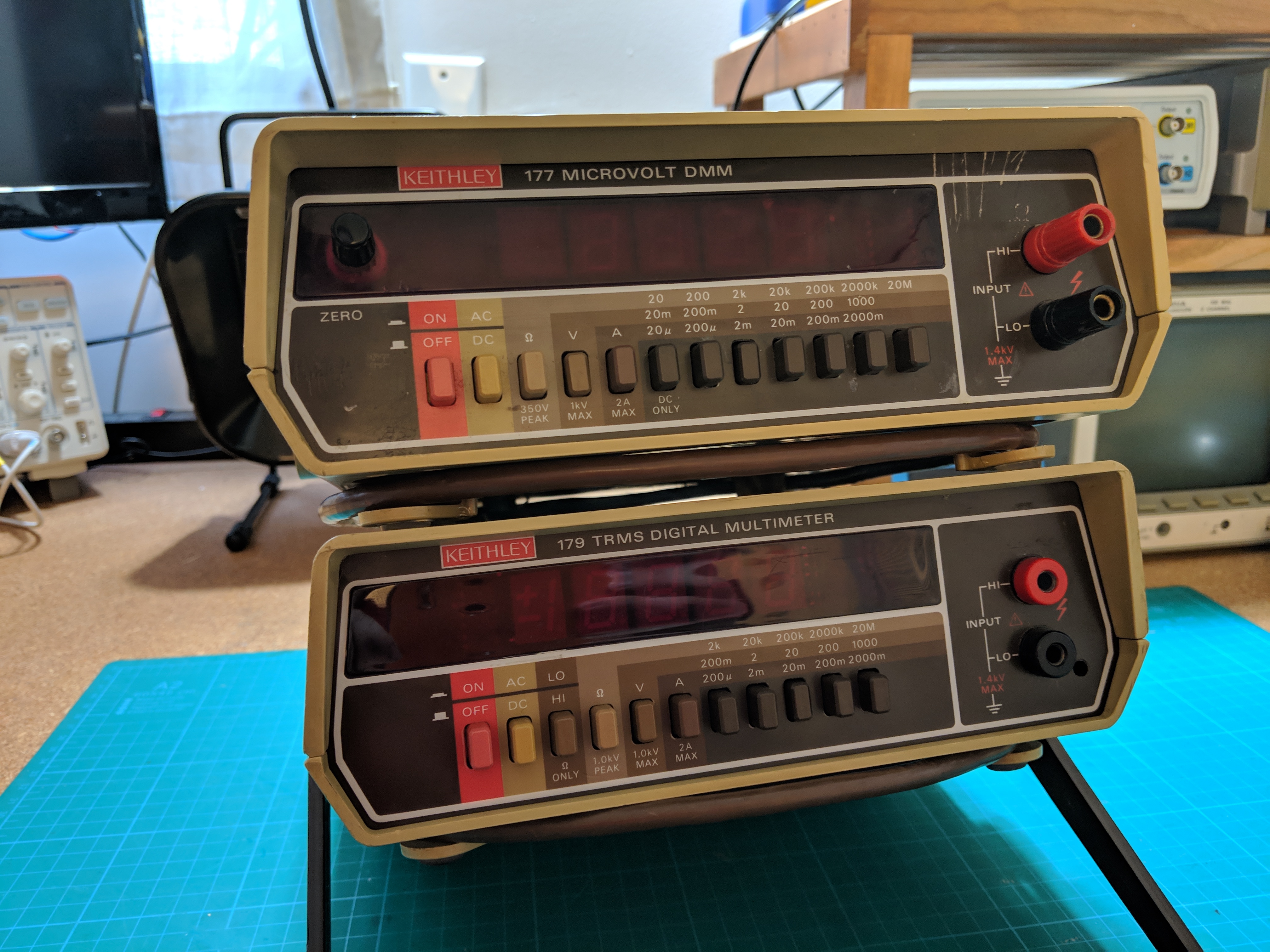
I picked up two used Keithley benchtop digital multimeters from eBay that are in need of repairs. They were sold as working but as is often the case with eBay sellers who are unfamiliar with measurement equipment, they both have some issues that I intend to fix in this short article.
The first step of repair that I take with all old equipment, especially equipment that uses ganged switches, is to clean the mechanical range switches with contact cleaner. I made sure to thoroughly soak each switch in the cleaner solvent before actuating each a few times to work out the grim and oxidation. While this did not fix any of the issues it does not hurt to start the repair with clean switches.
Repairing the Keithley 177
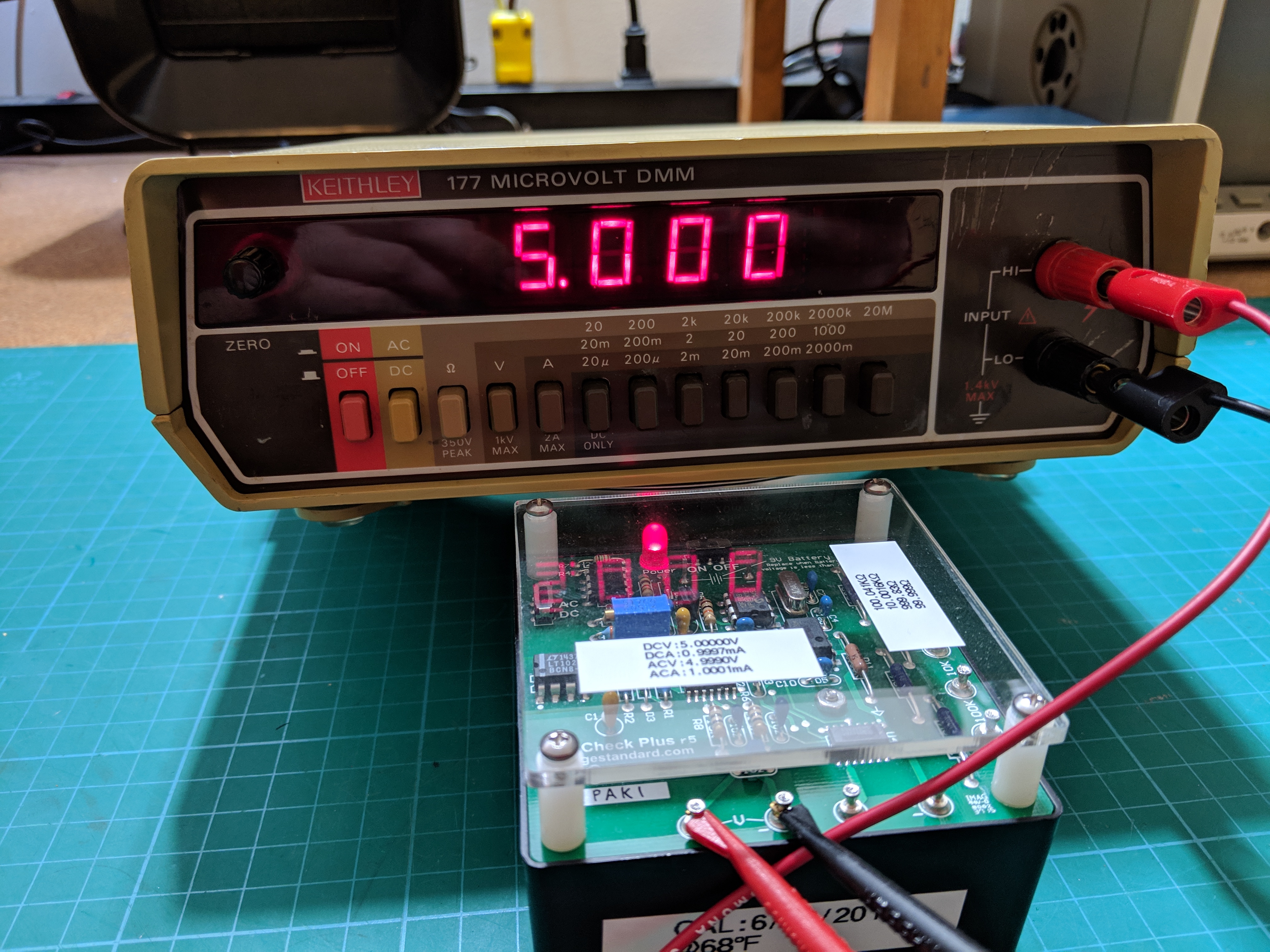
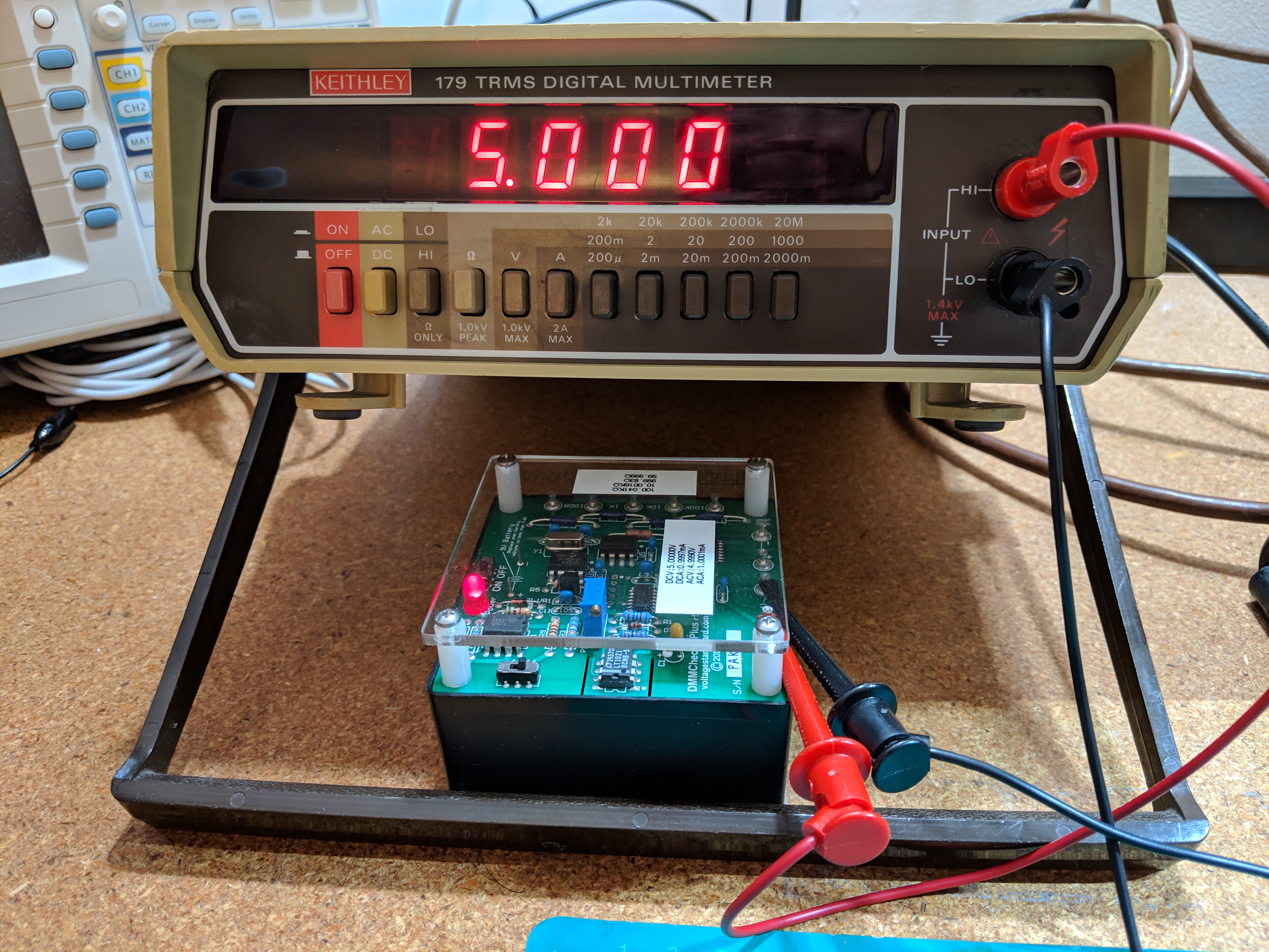
The Keithley 177 is the most functional of the two meters I picked up. The display works and using my DMMCheck Plus reference standard measures 5VDC well within its specifications, fluctuating by 2 counts at the most. Note that since I intend to use these meters mostly to measure DC voltage I haven’t checked the AC, current, and resistance functions of the meter.
The manual for the Keithley 177 can be found on a 3rd party website here, Keithley does not have it on their website. This is an ok copy of the manual but the schematic is not entirely readable. Luckily a user on the EEVblog forums posted an excellent copy of the schematic, look at the attachments in reply #2.
The issue with this meter occurs when the instrument is left running for an extended amount of time, the reading will begin to fluctuat well outside of its specifications. I verified with a second meter that it was not the voltage standard fluctuating. While writing this article I have left the meter powered and connected to my voltage standard for over an hour and have not experienced any issues, this may prove to be a hard issue to track down since it is intermittent or requires extended warm up time. I’ll go ahead with the repair based on my previous observations.
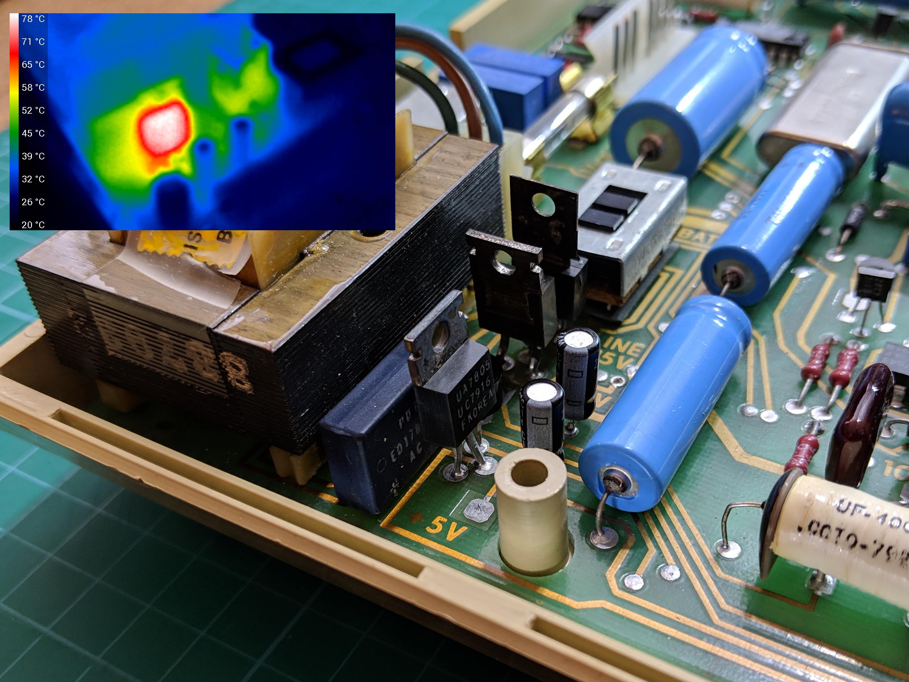
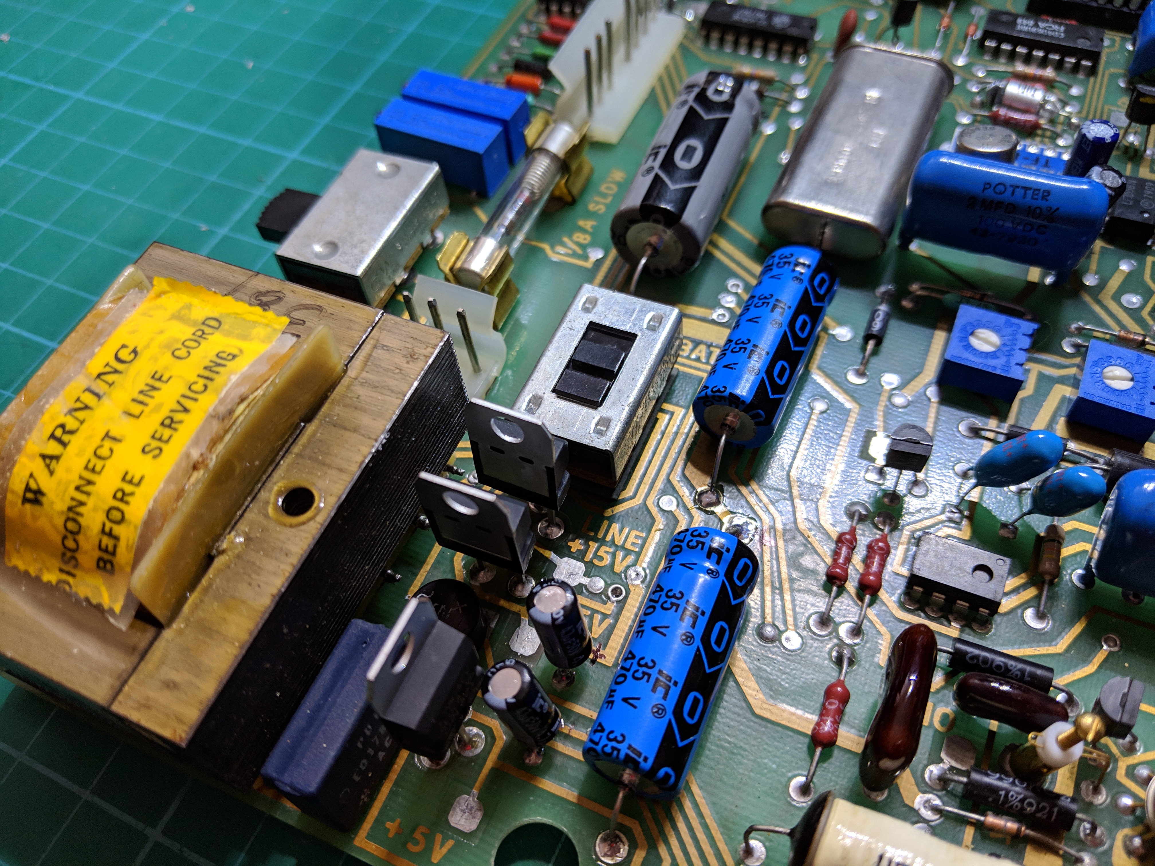
While probing around measuring the voltage rails and a few other test points I noticed that the voltage regulators were extremely warm. Using a thermal imaging camera the 5V regulator is almost 80C.
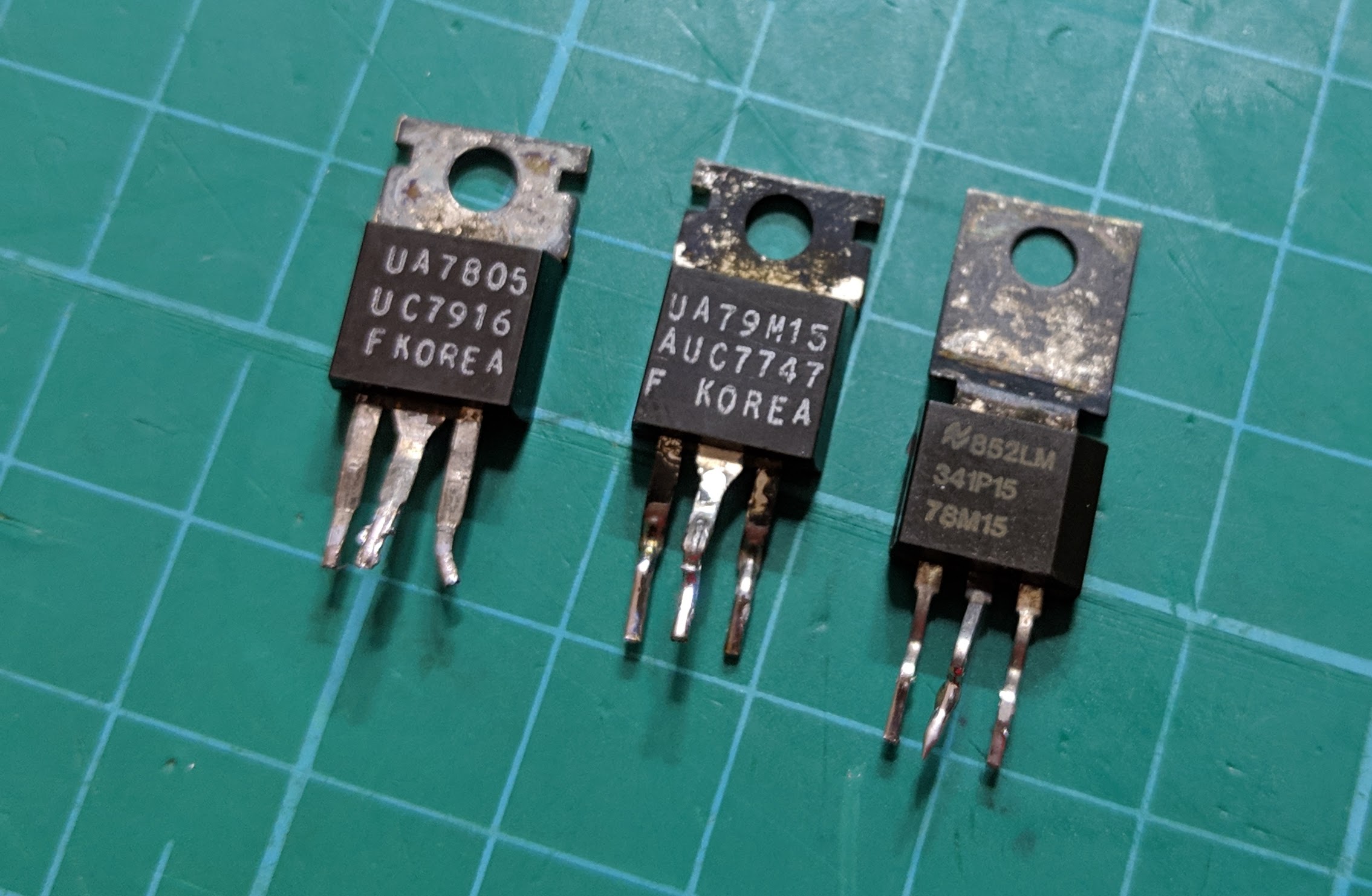
I replaced the 5V regulator and as a precaution the +15V and -15V regulators with new components. The large electrolytic capacitors appear to be original so I replaced those with new capacitors along with any of the tantalum capacitors that are across the power rails.

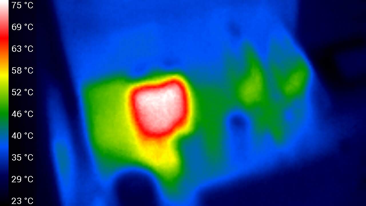
I was hopeful that replacing the 5V regulator would lower its temperature but as can be seen in the thermal image to the left that has not happened. Looking around with the thermal camera nothing else jumps out as being over temperature which would be a sign of excessive current draw. I replaced the original regulator with a L7805CV from ST that has a maximum operating thermal junction of 125C, maybe it is ok for this regulator to run around 75C and I am worrying about nothing. Still I grabbed a heatsink and slapped on on, it can’t possibly hurt.

That hopefully concludes the repair of the Keithley 177. I’m going to perform an extended test over the next few days to make sure the repair is complete. Currently I am looking into getting a DC voltage calibrator, an old Analogic AN3100, which will allow me to check more then the 20VDC range on this multimeter. Onwards to the next multimeter to repair.
Day After Update
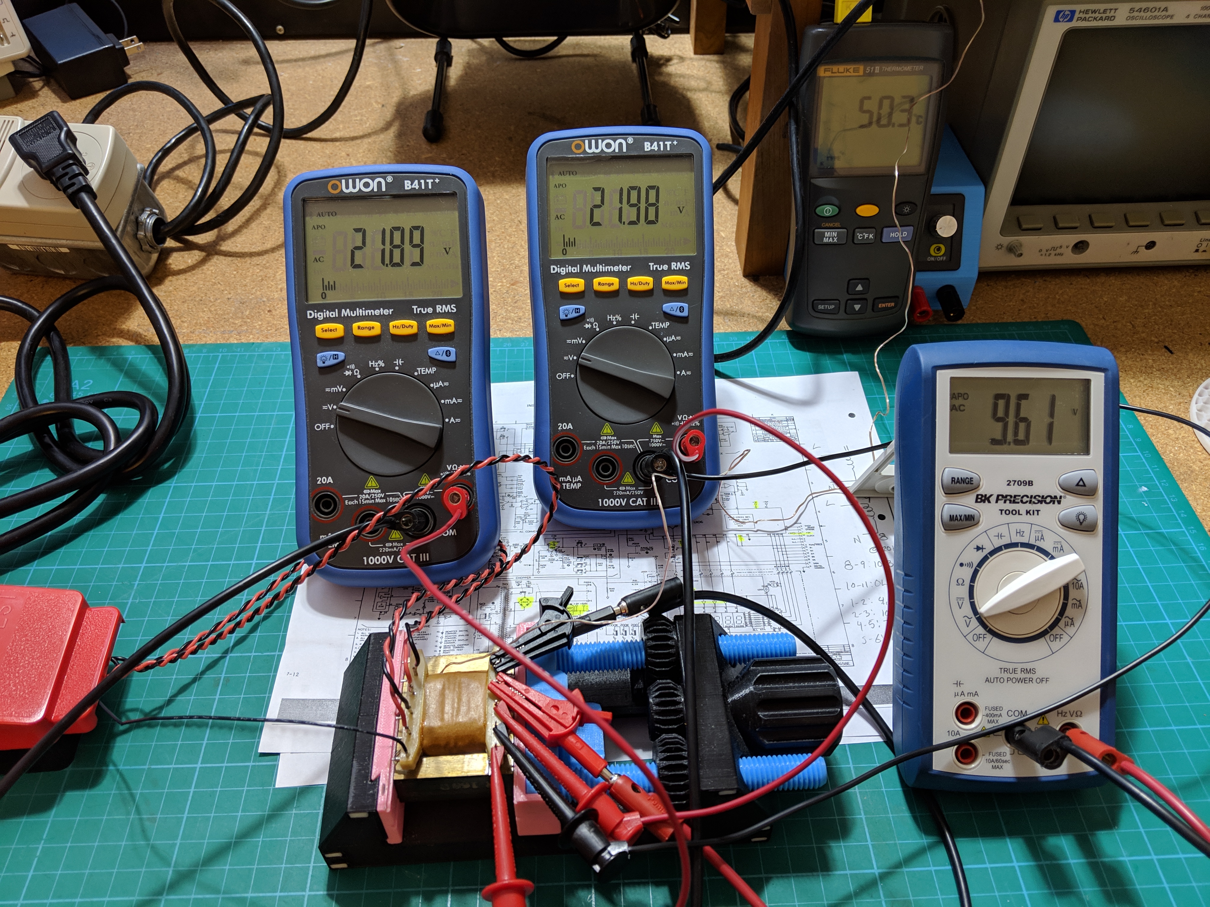
After replacing the voltage regulators and capacitors inside the Keithley 177 I left it running overnight connected to my voltage standard to ensure that there were no more issues. I woke up the next day to find the meter had blown its main fuse and the power transformer overheated. I pulled the transformer from the board and when powered with no load the transformer is overheating. This suggests to me that there is an issue with the transformer. I will look into replacing this component but it will require some searching and possibly a new power supply.
Repairing the Keithley 179

The Keithley 179 is unable to read any voltage applied to its inputs. The display flashes as if it is over range with the inputs shorted. This occurs on all ranges and functions. Luckily with this older equipment the user manuals offer great troubleshooting steps along with a schematic so that most repairs are possible if you know what you are looking for.
The manual for the Keithley 179 is available on the Keithly website. The schematic and manual is a good readable copy of the original. After following the first rule of troubleshooting electronics and finding that all the power rails were well within specification I began to suspect an issue with the internal voltage reference. Table 5-4 A/D Converter on page 5-5 starts with troubleshooting of the internal voltage reference.
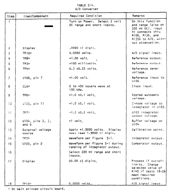

My suspicion about the voltage reference circuit was confirmed when I found that TP8 had a voltage of 0.49V, not the specified 1.00V, and TP3 had a voltage of 68mV instead of 100mV. The zener reference voltage, TP4, was 4.3V, lower then the required 6.3V +-0.25. I must admit that I then wasted a lot of time trying to understand the voltage reference circuit by studying the schematic, probing around, and setting off on wild goose chases until I concluded that the problem was a damaged IC, the Intersil ICL8052ACPD. Since the Keithley 177 uses the same chipset as the 179 I swapped this IC and found that the meter now worked without any issues. Luckily this appears to still be a common IC with a few sellers offering new old stock on eBay for under $4 plus shipping, I ordered two just incase. Popping in the new IC yielded a working multimeter.
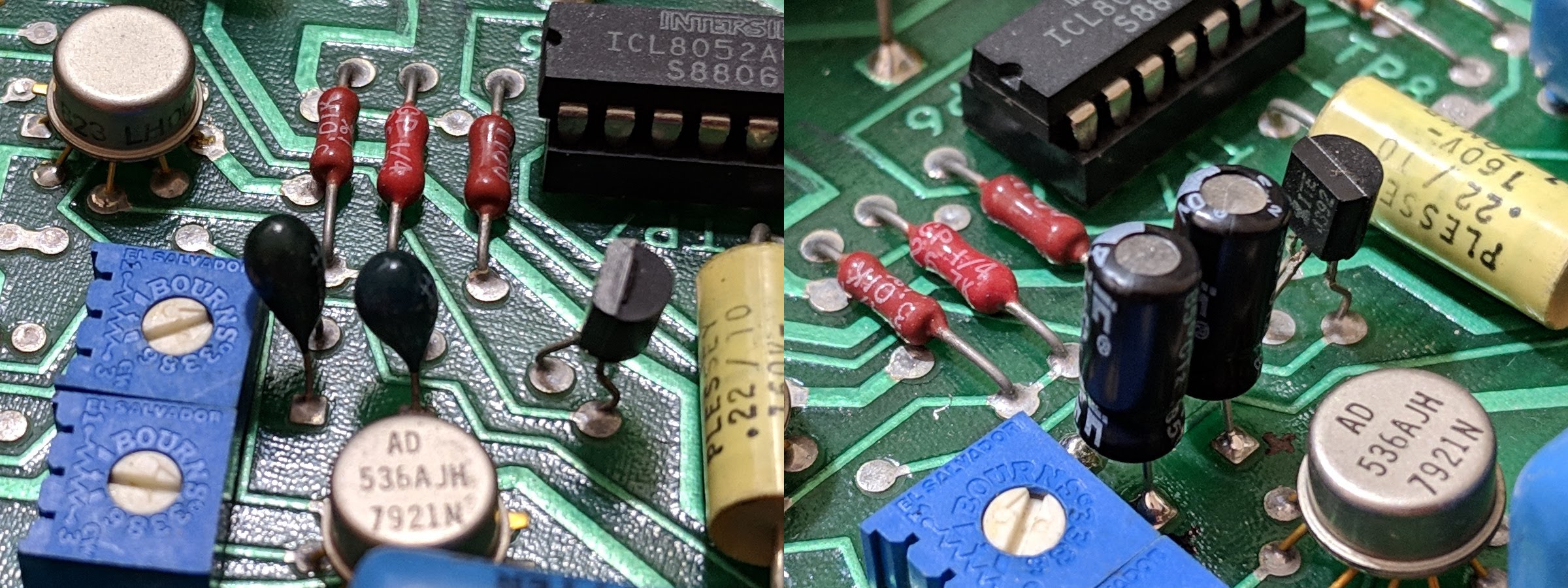
While I had this meter open I went about replacing the tantalum capacitors across the +15V, -15V, and 5V power supply rails. I am not sure what caused the Intersil IC to fail but if it was a power rail spike then these tantalum capacitors would have seen that spike and are known to fail after experiencing such a spike. I replaced these with aluminum electrolytic capacitors, if I experience problems I will spend the extra money for tantalum replacements in the future. I was sure to note the polarity of the capacitor before removing them by placing a small marking on the PCB next to each positive pin. In the end I replaced all but two of these tantalum capacitors, C115 and C116 are 33uF 15V capacitors that appear to be AC decoupling capacitors for the input to the TRMS converter.
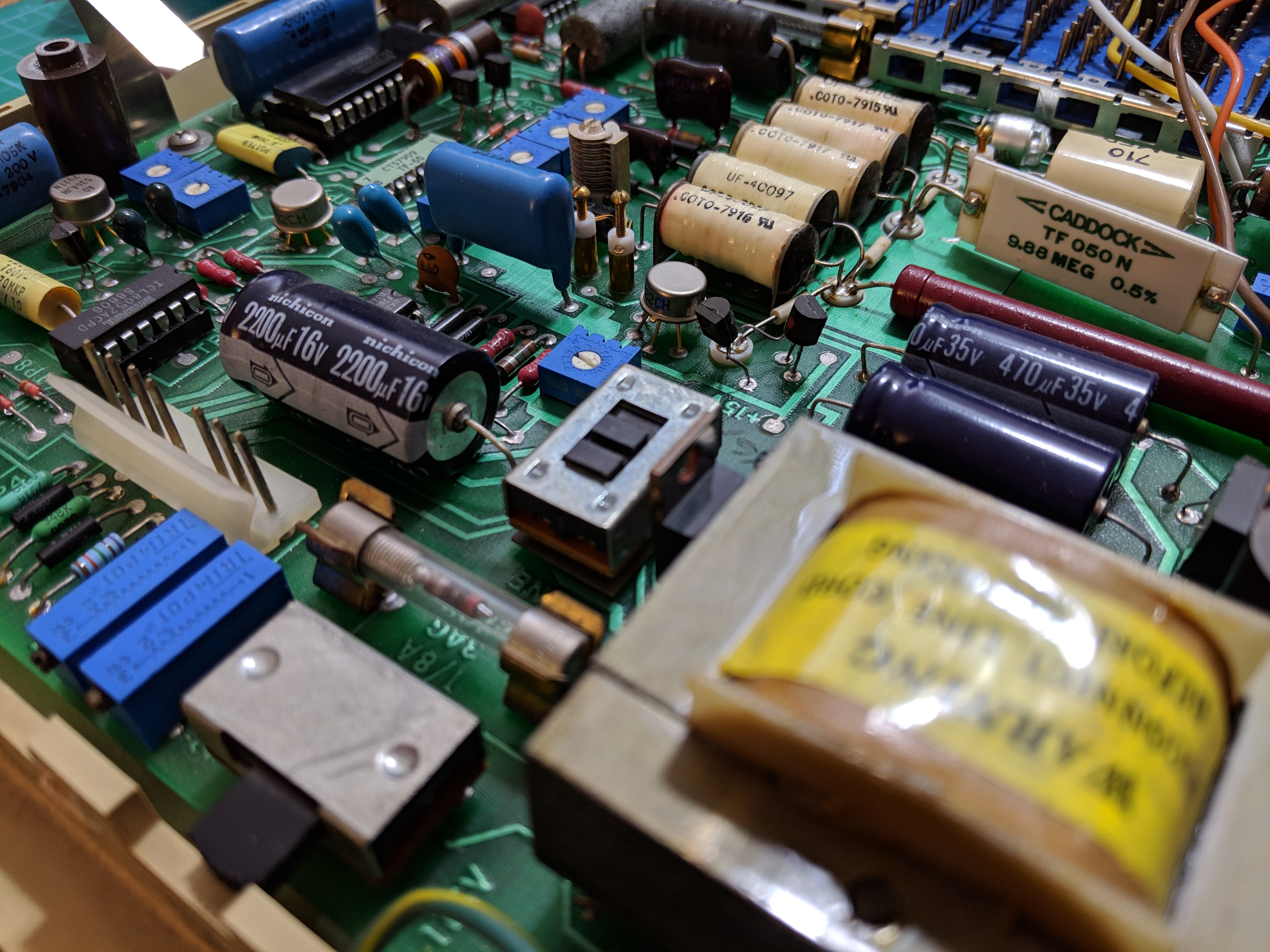
I did not replace the large aluminum electrolytic capacitors since they appear to have been previously replaced with newer Nichicon capacitors. Speaking of past repairs both the +15V and -15V regulators have been replaced with newer components, confirming my suspicion that a power supply failure damaged the Intersil IC. As a precaution I replaced the old uA7805 regulator with a new L7805CV regulator since the old 5V regulator was discolored. As a final touch I removed all the flux residue from my repairs and the previous repairs.
That concludes the repair of my Keithley 179 multimeter. I still have to verify all the ranges and functions along with checking the meter over a few days to make sure there are no intermittent issues but I believe this meter is fully functional and ready for use.
Is That All?
Aside from checking the calibration on these two meters I should be done with the repairs. I do have a few additional modifications I would like to make to these meters. The first is to replace the built in power cord with one of the IEC power connectors that are found on all new equipment today. I hate non removable power cords and this should be a simple enough replacement only requiring a square hole cut into the back of the enclosure. I also want to be able to use these meters for data logging so I would like to add a serial output port that would send the meter’s reading to a connected computer. Luckily there is a connector on both models that was originally designed for a GPIB addon feature. This is connector J1008 on the 177/179. The schematic outlines what each pin on this connector is used for. This should be an easy task for an Arduino and will definitely be a future article.

2 thoughts on “Benchtop DMM Keithley 177 and Keithley 179 Repair”