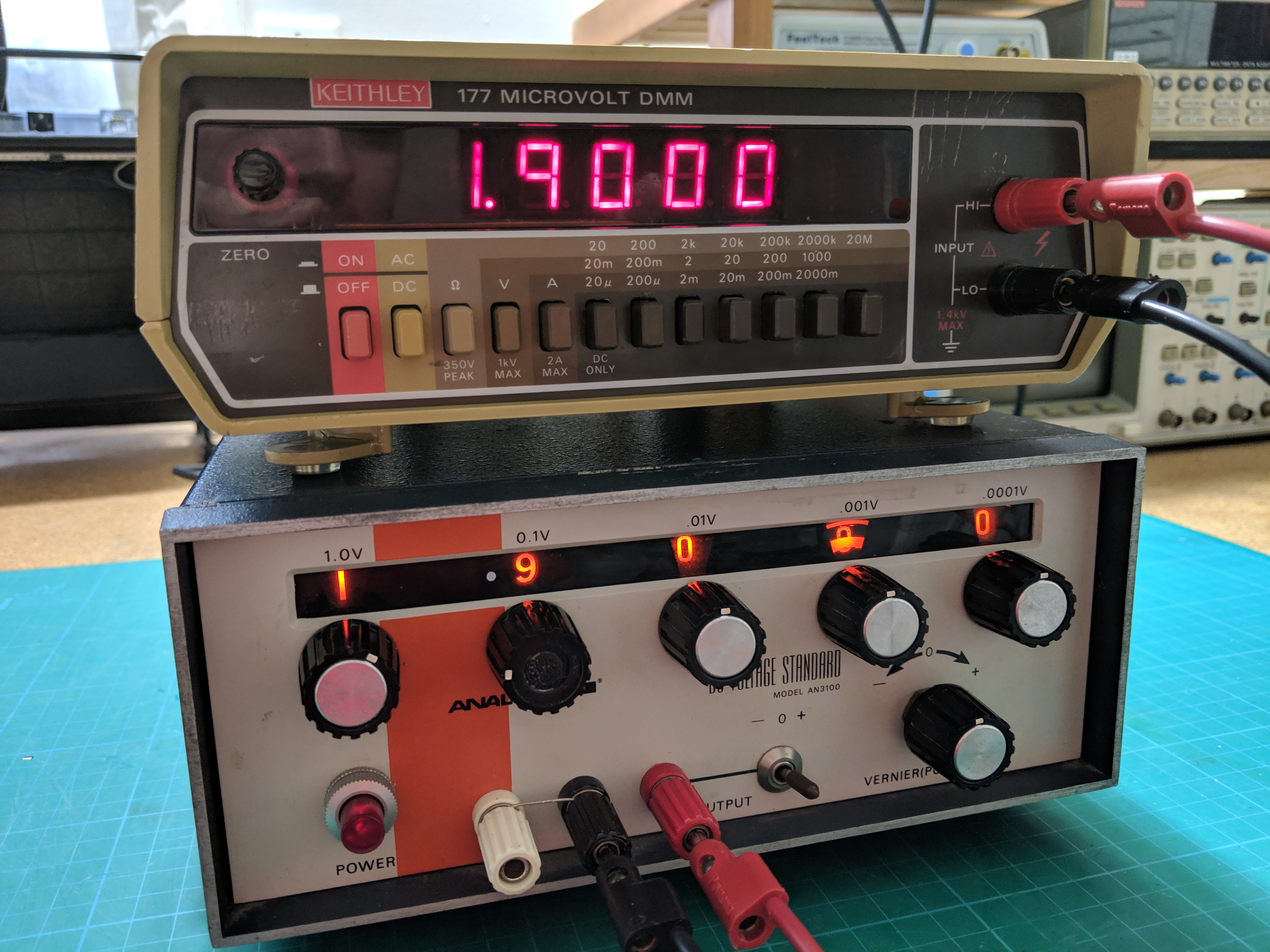
After picking up and repairing two Keithley multimeters I found it necessary to have a way to calibrate them. I have a DMMCheck Plus voltage standard but that is set to a fixed 5VDC, not very useful when the calibration procedure calls for 1.900VDC. Luckily I was able to pick up a used Analogic AN3100 DC Voltage Standard, a 0.005% of reading accuracy reference standard with a voltage range of 0 to 11.000VDC. Of course this unit requires repair and calibration before use.

Like a Broken Record, Electrolytic Capacitor Replacement
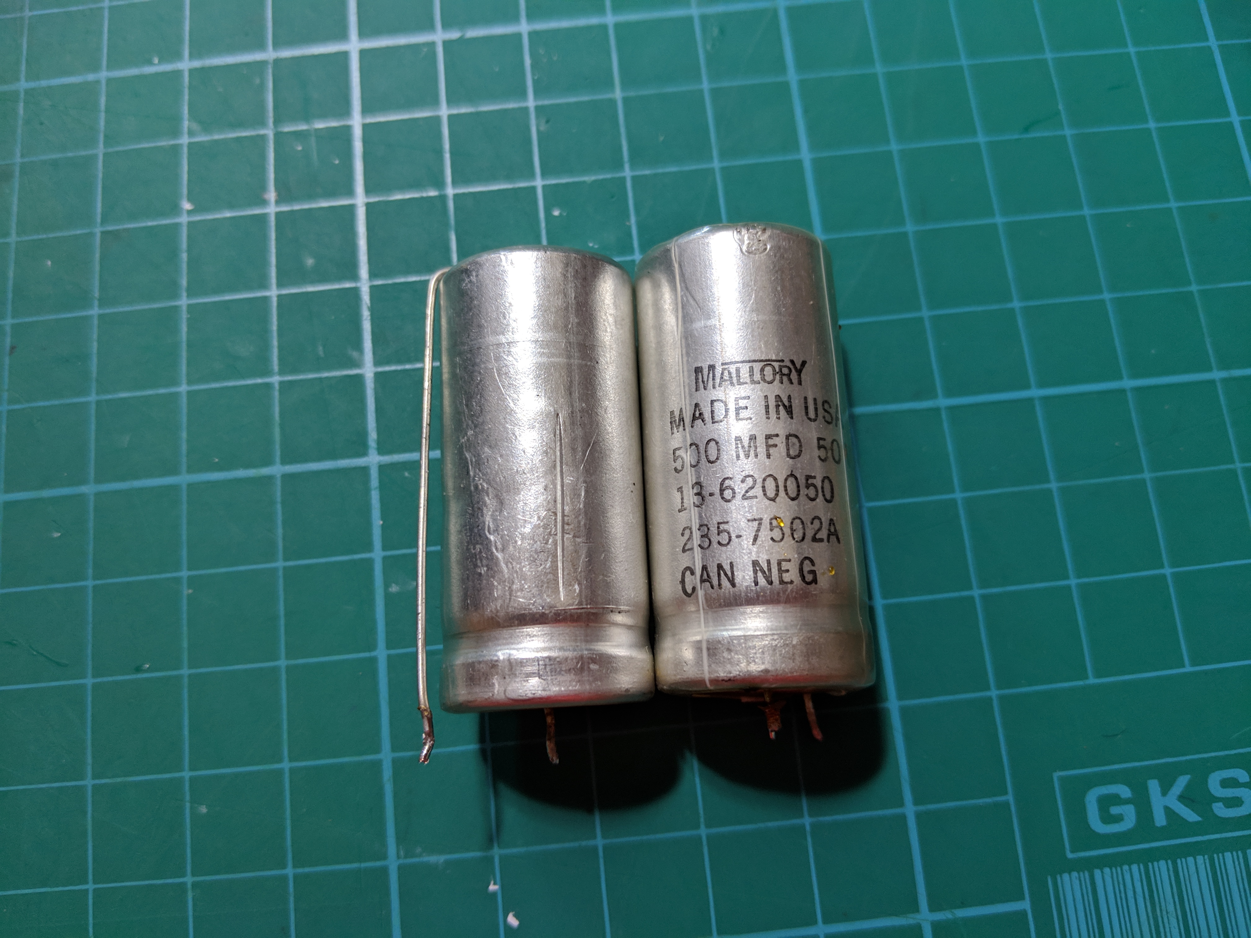
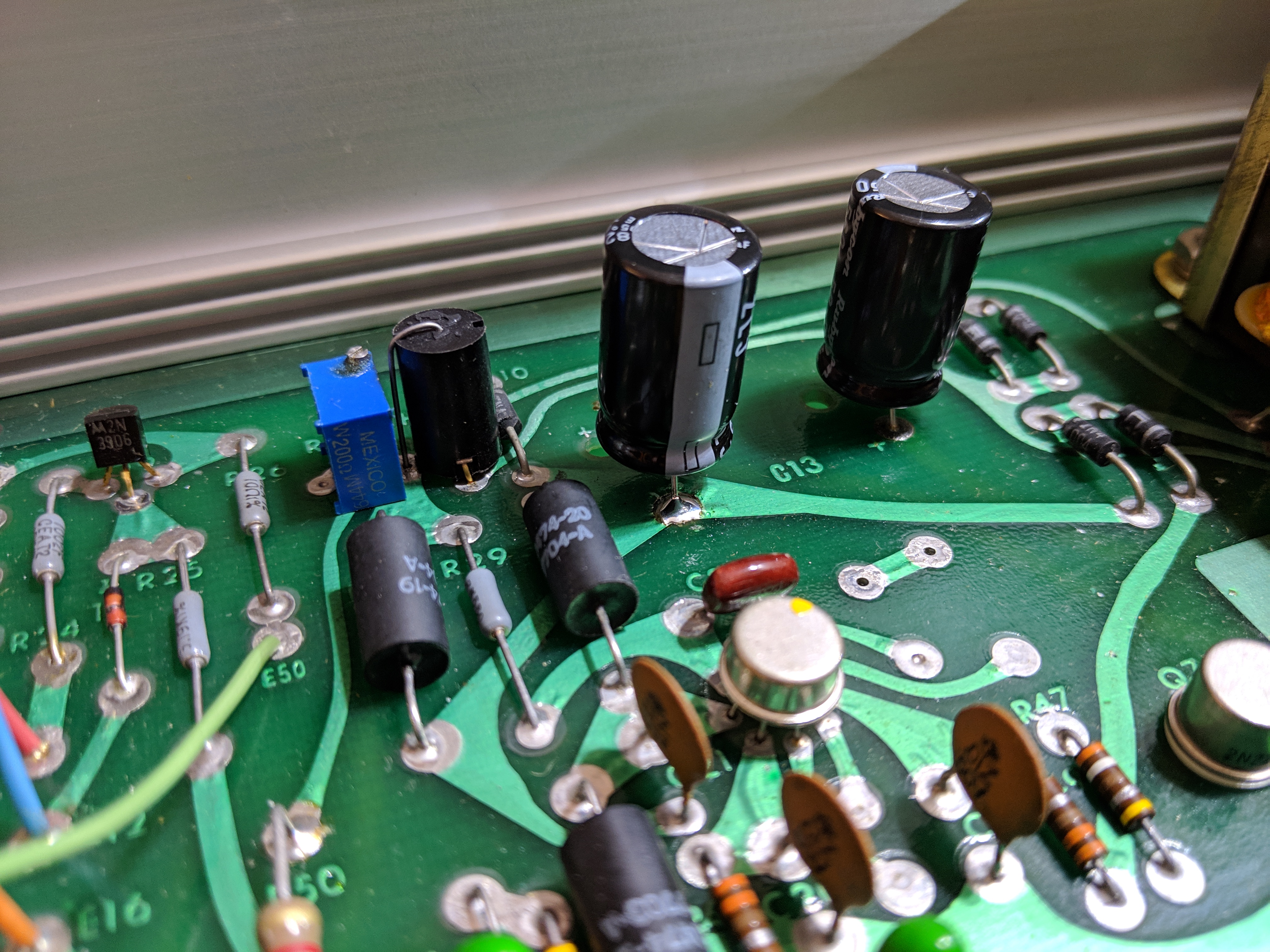
First order of business with all old electronic equipment of a certain age is to replace the electrolytic capacitors. I replaced the only two electrolytic capacitors in the unit, Mallory 500uF 50V, with Rubycon 560uF 50V. I went with slightly higher capacitance because the only 500uF 50V capacitor available from DigiKey at the time cost $13 each! By comparison the 560uF 50V Rubycon capacitor was $0.73 each, I believe mainly because 560uF is a standard capacitance value whereas 500uF is a nonstandard value.
This would have been a super simple repair except for the fact that one of the pads lifted during desoldering requiring a little ingenuity to repair in the form of soldering the component lead on the other side of the board.

Voltage Output Stability
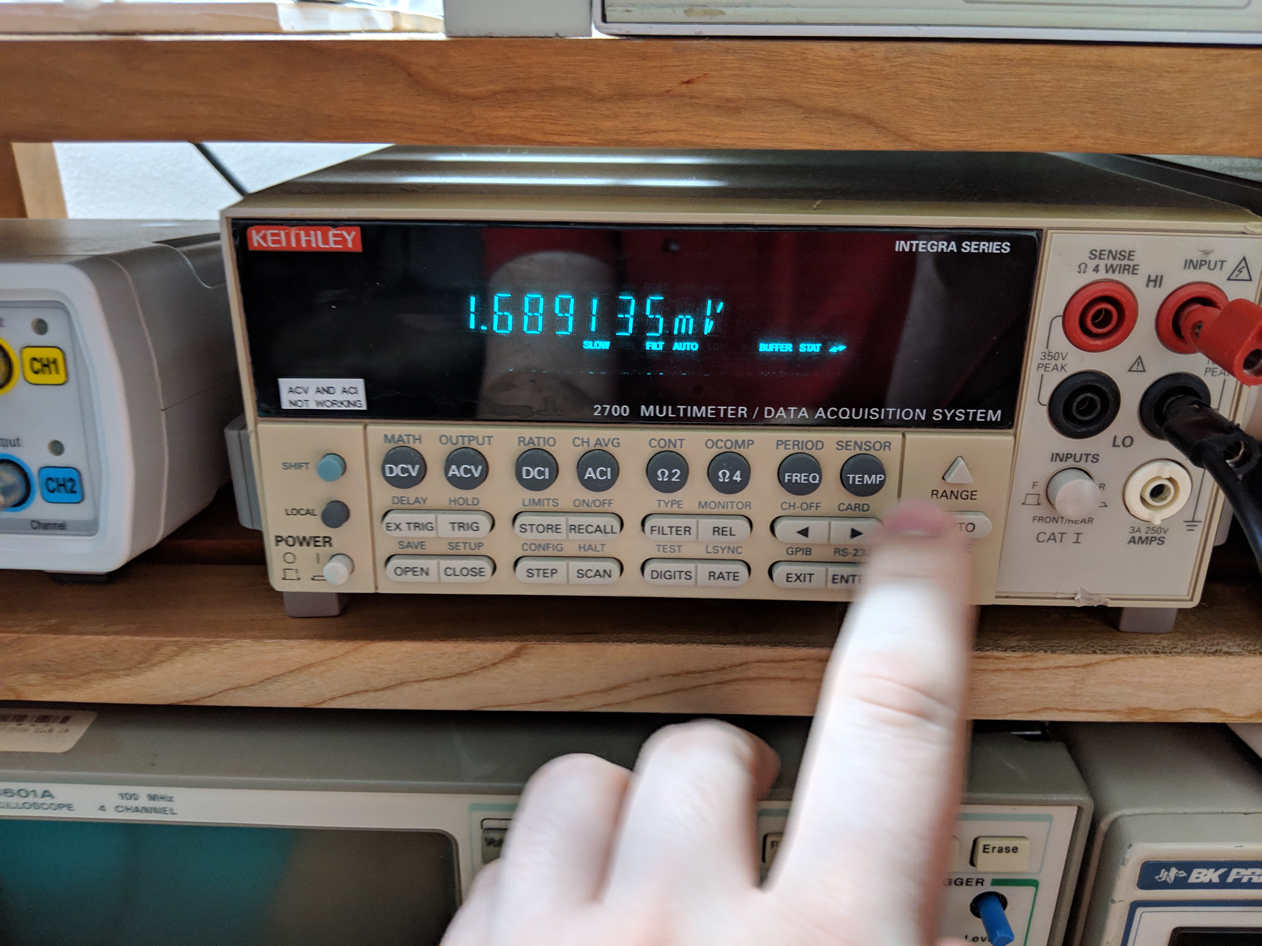
I connected this unit up to my Keithley 2700 6.5 digit multimeter to check the output voltage stability of the Analogic and found that it had a peak to peak voltage of ~2mV. Since this unit has an accuracy of 0.005% of reading, at 1V a fully functional unit should not vary by more than ±50uV. A 2mVp-p reading suggests a damaged unit. Time to find a manual.
I found a usable manual on a hifi forum here. The manual and schematic are readable and seem complete. I also found another manual with a slightly better schematic by searching for the Data Precision VS8100, they are the same unit just under different names.
Following the troubleshooting flowchart in figure 4.2.1 of the manual I was able to determine that the 30VDC measured from the cathode of diode 6 to the anode of diode 9 measured 24VDC, below the required ±10%.

A low 30VDC rail causes the ±15VDC rails to fall well below spec. Now that I was sure I found the cause of the high output voltage ripple I need to determine what was causing the voltage rails to be so low. Looking around with my thermal camera nothing jumped out as a shorted or damaged component so I started poking around with a multimeter.
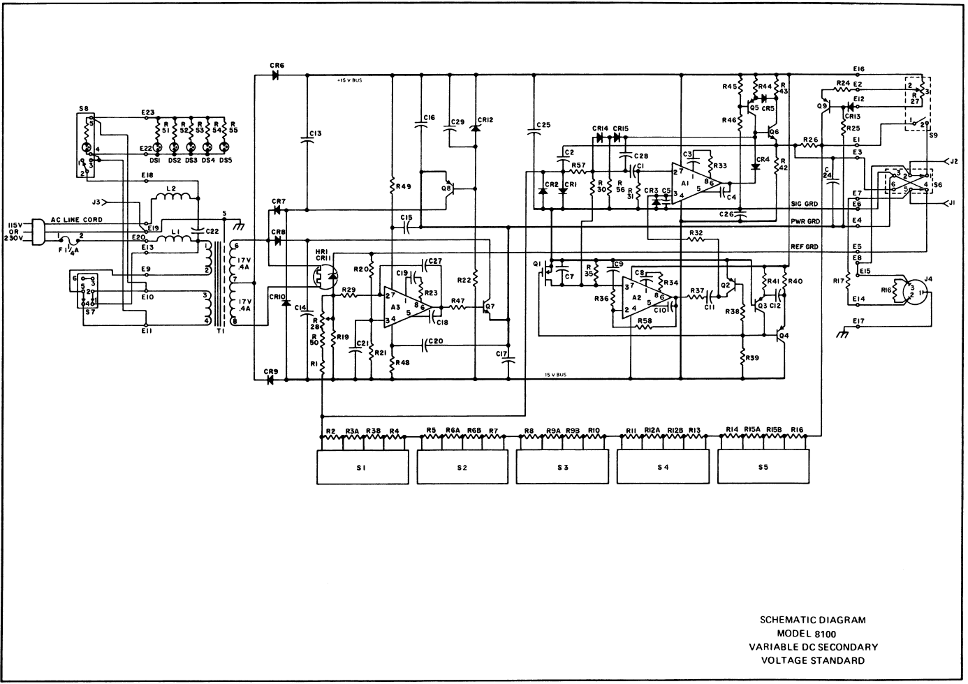
I was able to track it down to one of the AC rectifying diodes, CR6. With the unit unplugged and using a multimeter on diode mode I found that CR6 was open. When I removed the diode from the PCB and measured it again I found that its forward voltage would fluctuate based on the force applied to the component leads, the diode had failed.

Replacement of diode CR6 with a 1N4007 diode brought the 30VDC rail up to 28.3VDC, well within the ±10% spec and also brought the ±15VDC rails within spec. Measuring the output ripple I found that at 1V the peak to peak voltage was 1.66uV.

The unit was now fully functional and I was able to check its output voltage against a calibrated voltmeter to confirm it was still within its 0.005% spec. With this unit I can now calibrate the DC voltage range on my newly acquired Keithley 177 and 179 multimeters.