The following device is used to connect the Keithley 177 and 179 digital multimeter to the PC. The USB Adapter is a serial COM port enabling the user to use simple serial terminal programs to read data from the Keithley multimeter. The device fully isolates the PC from the multimeter through optoisolators and has no impact on the meters performance. The Keithley 17x USB Adapter is a simple device for connecting two great multimeters to the PC to further increase their value to hobbyists by enabling data logging.


Top View 
Bottom View
The Keithley 177 and 179 Digital Multimeter have a GPIB option. If your meter has this option installed you may want to get a GPIB to USB adapter and use that. If your meter does not have this option installed then the Keithley 17x USB Adapter is for you. The original GPIB option was a daughter board that connected to the meter’s main board using connector J1008. This connector is a 14 pin DIP socket located right behind the input terminals of the meter. Before continuing with the project I suggest you open up your meter and locate this connector. Below are pictures of the socket location on the three meters I have. If the socket is not soldered in but the footprint is on the PCB then don’t worry. Get a suitable DIP socket and solder it in.

Keithley 177 J1008 location 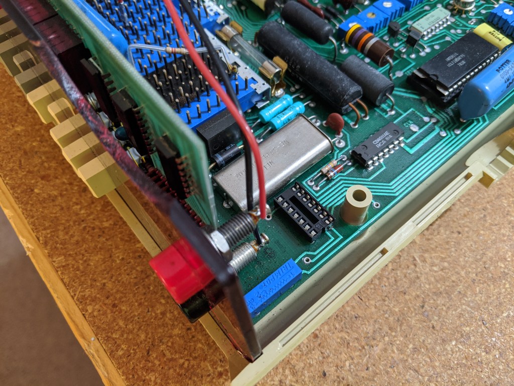
Keithley 179 J1008 location 
Keithley 179 J1008 location
Building the PCB

- Download the GERBER files and order from your favorite prototype PCB board house. The PCB is double sided and is 70.5mm x 40mm in size.
- For reflow soldering I strongly suggest getting a solder paste stencil from your prototype PCB manufacture. If ordering thorough a board house that does not offer stencils then OSH Stencils is a low cost option. The polyimide film 3mil stencil is more then durable enough for a few boards and the cost is just about right. For hand soldering the solder paste stencil can be omitted.
- Order the components listed in the BOM. All items were ordered from DigiKey or LCSC but it is possible to source from other suppliers.
- Use the Interactive BOM for part placement during PCB assembly.
Programing the MSP430FR2110
- The lowest cost solution to obtain a programmer for the MSP430 is to buy a TI Launchpad. The MSP-EXP430FR2433 Launchpad is a good option but any TI Lauchpad that has an onboard eZ-FET debug probe will work.

- There are at least two software paths for uploading the firmware
- TI UniFlash: You can either install UniFlash or use the UniFlash cloud tool. The compiled code is in firmware/releases.
- TI Code Composer Studio: Install the latest version of Code Composer Studio, import the CCS project found in firmware/keithley_17X_USB, and build the firmware yourself. There is also a cloud version of CCS that you can use if you do not want to install software on your PC.
- Remove all the jumpers from the TI Launchpad used to connect the eZ-FET to the onboard target microcontroller. Connect the eZ-FET to connector J3 on the Keithley 17x USB adapter. The pinout is labeled on the silkscreen. It is not necessary to solder a header onto the PCB, I programmed all my boards using female to male Dupont wires and held them in place while uploading the code.

remove jumpers 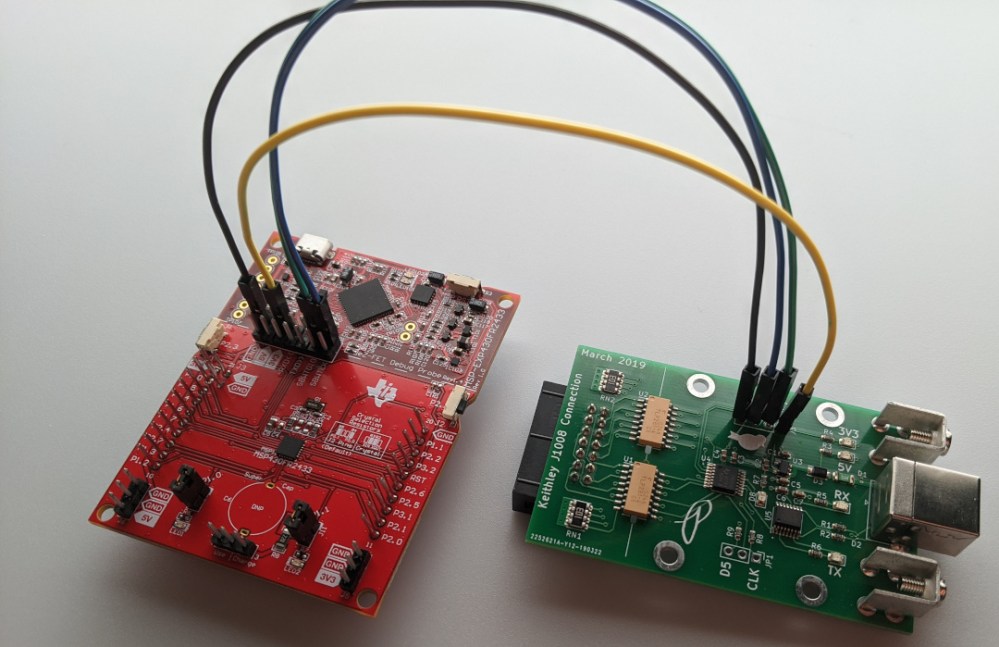
eZ-FET connected
Installing the USB Adapter into the Keithley Digital Multimeter

- Print and cutout the mounting hole locating template.

- Open up your digital multimeter. We need to add a few holes to the rear of the top case.
- Using a punch and the hole locating template, mark the center of the mounting hole locations and the USB cutout.

- Drill the mounting holes using a #29 [3.45mm] drill or closest metric size. Enjoy that old plastic smell coming from the fresh drilled hole.
- I recommend pilot drilling the USB hole first, you can use the same size drill bit from the previous step. Then drill the USB cutout to 5/8″ [15.875mm] or the closest metric size. I used a set of step drills so that the hole was gradually increased.

pilot drill USB hole 
check USB fit
- Don’t forget to deburr the drilled holes.
- Print off a face plate so we can hide the gap around the circular cutout for the USB connector. Print at 0.2mm layer height. It’s very thin so it should print fast, about 5 minutes on my Prusa clone. If you don’t mind the gap you can skip this.

- Place the top of the case to the right of the bottom of the multimeter.

- Install the DIP connector into the DIP socket on the multimeter main board. It’s hard to see it in the photo but the DIP socket has a chamfered corner on the inside pocket to indicate pin 1. Align pin 1 of the DIP socket to pin 1 of the ribbon cable, the red stripe. Don’t go by the pictures below, it seems that the placement of Pin 1 on this DIP socket is different not only between the 177 and 179 but also between the same model number.

align pin 1 of connector and socket 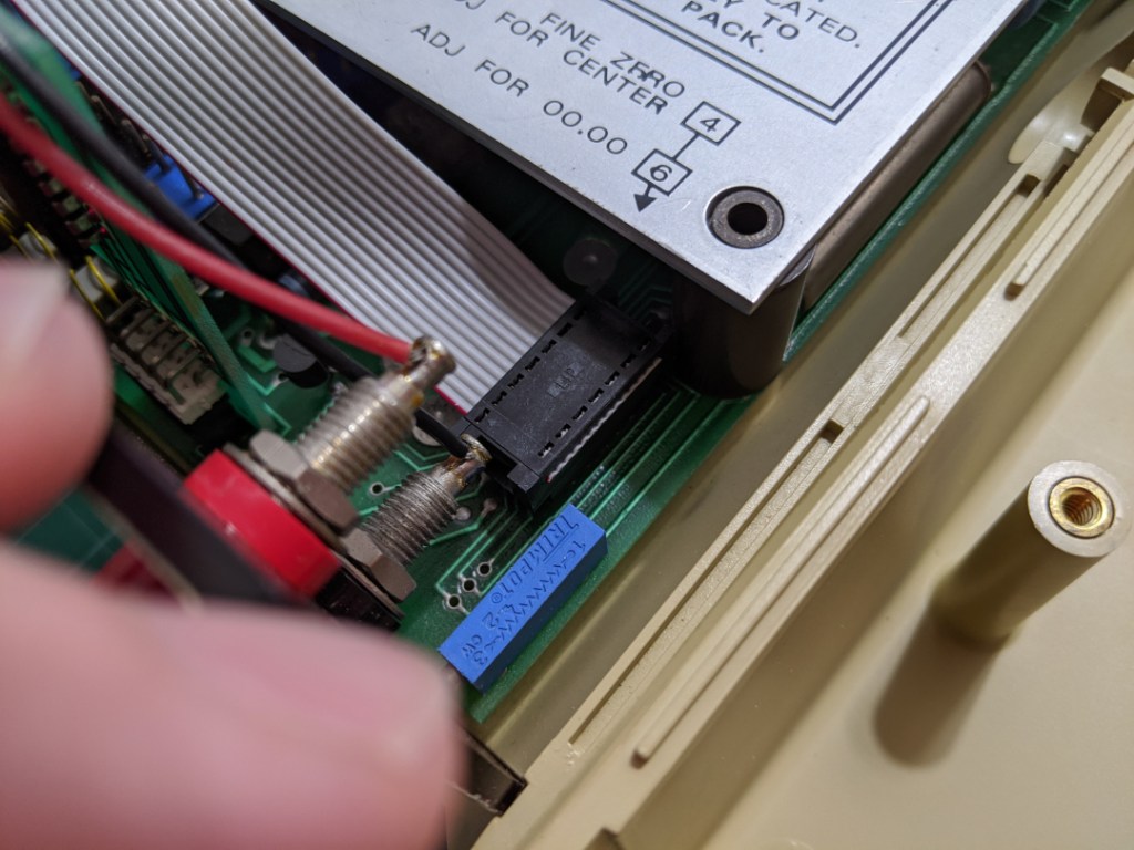
connector installed
The DIP socket on my 177 was to close to the mounting pillar and required me to shave off the corner of the DIP connector.

- Install the IDC connector on the ribbon cable. Pin 1 of the connector is indicated by a small triangle, make sure this aligns with the red stripe of the ribbon cable. Before fully attaching the IDC connector it is good to check the cable length by putting the top of the case onto the multimeter.

IDC pin 1 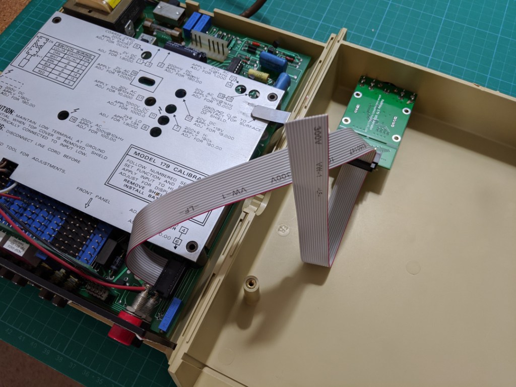
checking cable length
- Trim the ribbon cable. A hobby knife or similar tool works.
- Reassemble the multimeter and test it out using a serial terminal program on your PC.

trim ribbon cable 
test it out
PC Connection
The Keithley 17x USB Adapter uses a FTDI serial to USB converter IC. Most operating systems should come with drivers already installed. If your system does not come with FTDI drivers you will need to download and install them from FTDI.
Connect to the Keithley 17x USB Adapter using any serial terminal program such as PuTTY (Windows) or Minicom (Linux). You can also use the Arduino serial monitor. The Keithley 17x USB Adapter is setup for a baud rate of 115200 8N1.
Python GUI
If you have Python 3.x installed on your computer you can also use the Python GUI. Run the GUI from a terminal using the following command:
python Keithley_17X_USB/software/17X_UART_Reciever/main.py
Select the model of multimeter you are connecting to. A window will popup that will let you select the serial port of the multimeter you want to connect. After connecting select the measurement units and the measurement range of the meter. The range switches on the GUI do not change the range on the multimeter, they simply format the GUI display to match the multimeter display. There is no way for the USB Adapter to change the range on the multimeter, it is a read only device.

Theory of Operation
Below is a screenshot from the display section of the schematic for the Keithley 177, the 179 display is similar. Connector J1008 is on the right of the schematic. This connects to the data bus between the main multimeter IC U106 and the display. The USB adapter taps into this data bus to decode the data being sent to the display.
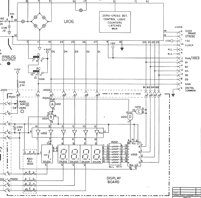
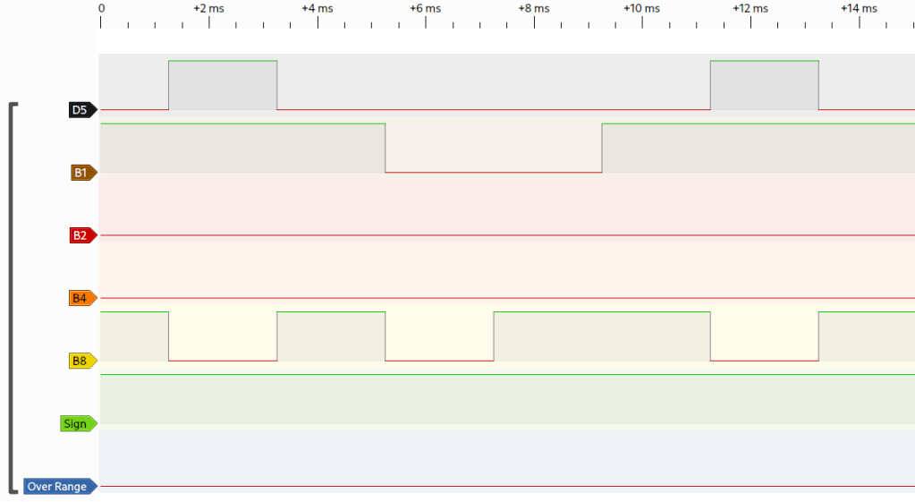
The D5 signal is high when the fifth digit on the display is on, the fifth digit is the left most digit when looking at the display. This signal is high for 2ms. B1, B2, B4, and B8 are the four bit value that this display is showing. In the logic analyzer capture below only B1 is high therefor digit 5 is 1. Since the other digits are not available on this data bus the USB Adapter hardware triggers off a rising D5 signal and then uses hardware timers to sample the remaining digits which are all 2ms in length. The above example decodes to 19089. Notice how there is no signal for the decimal place on the data bus available to the USB adapter. Since the sign signal is high that means that the value displayed is positive. The overange signal will strobe high and then low signaling that the meter is out of its measurement range, this signal was not outside of the range since I was connected to a 1.9000V reference and the meter was in its 2V range.
What about Clock? The clock signal is ignored by the USB adapter since it was not consistent across the two meter models that this project was targeting. You may notice that JP1 of the USB Adapter seems like it was put there as a way to select the conversion trigger off of the D5 or Clock signal. You are not wrong, that was my original intent but I found it was easier to only trigger off of D5.
GitHUb Repository
All design files and source code has been uploaded to the GitHub repository: https://github.com/sdp8483/Keithley_17X_USB
You can also buy the USB Adapter as a kit on Tindie, you can purchase it here:https://www.tindie.com/products/sdp8483/keithley-17x-usb-adapter/


I’ve got a 177, so I’m interested.
I’m not one to claim any proficiency messing with SMT parts, I
have trouble just seeing them. So I would like to know if it’s
available as a preassembled and tested “kit” and the cost.
Dave – AC2GL
All typing errors are my own work and subject to copyright laws, except
errors by the spell checker which generated by Artificial Ignorance (AI)
LikeLike
Thanks for your interest and I have a few spare kits that I would be happy to sell.
I listed them on Tindie for purchase: https://www.tindie.com/products/sdp8483/keithley-17x-usb-adapter/
LikeLike