Introduction
The hardware and code presented below is designed to simulate the sound of a train horn (or come as close as possible with the given hardware). Specifically is is designed to synthesize the sound of a Leslie S-3L Locomotive Air Horn.
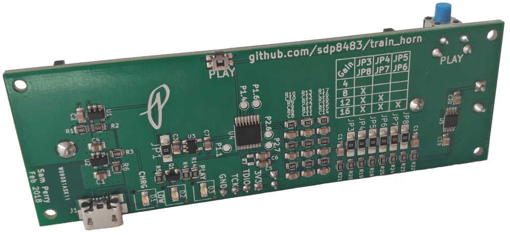
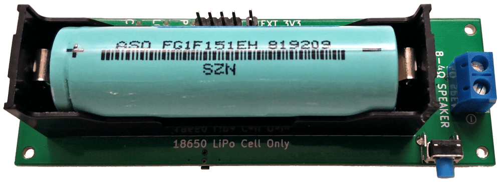
The final design is battery powered for portability. It uses a 18650 LiPo cell and features an onboard charger using a standard micro USB port and a low battery indicator LED.
The circuitry is able to drive a standard speaker load of 8-4Ω for mono sound. Four adjustable gain settings of 4, 8, 12, and 16 are available for setting the output volume of the audio amplifier with minimal modifications.
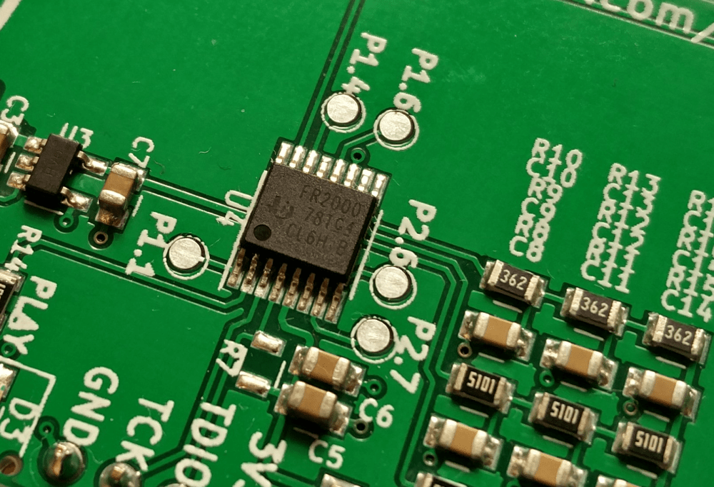
An onboard microcontroller generates the chord and enables the user control of the sound though a simple push button. The MSP430FR2000 was chosen due to its low cost in single quantities and availability at the time of designing this product. The MSP430 line was chosen specifically to develop a familiarity with using the product.
A Brief Overview
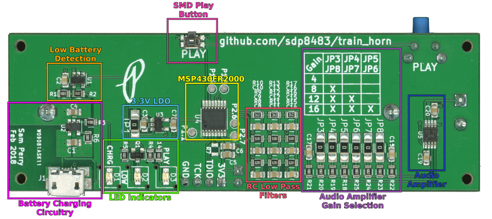

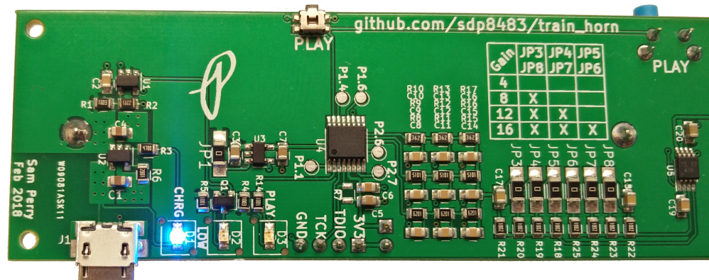
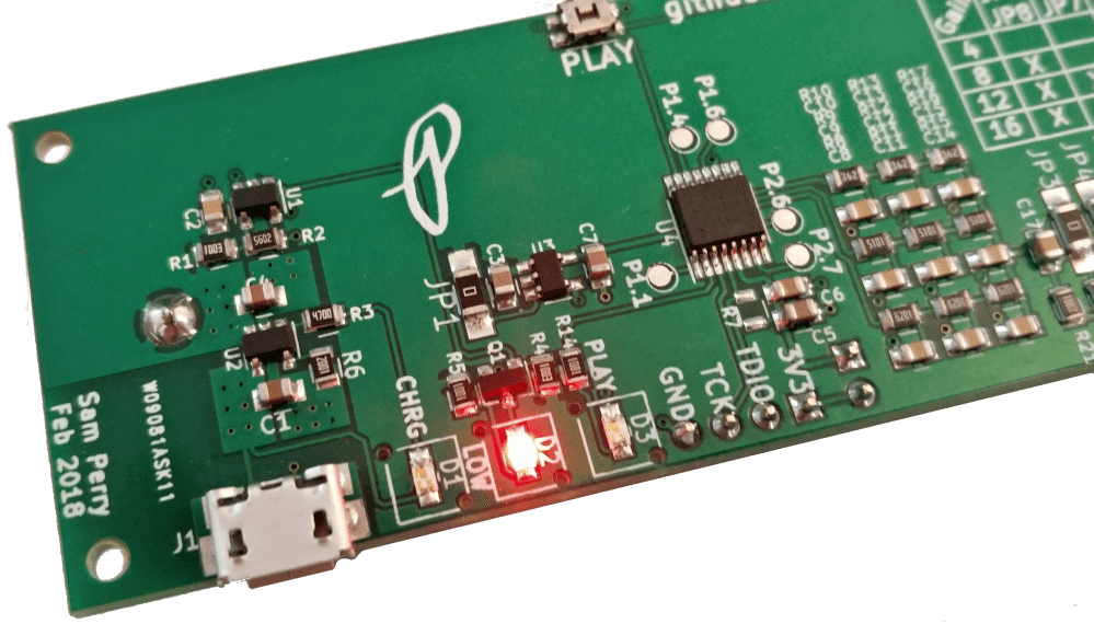
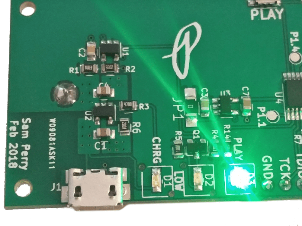
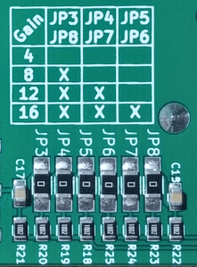
A 4-8Ω speaker is connected to the speaker terminal. The device is powered from a 18650 LiPo cell which is charged using the micro USB port, a blue LED indicates that the battery is charging. The charging circuitry is capable of charging the battery at a maximum current of 500mA. The low battery detection circuitry will illuminate a red LED indicator light when the battery voltage is low and requires charging. The audio amplifier gain (volume) is configured using jumpers JP3-JP8 and is set to 16 by default. Pressing and holding either the small SMD or the larger right angle play button generates sound. A green LED is illuminated while sound is playing. Releasing the button stops sound generation.
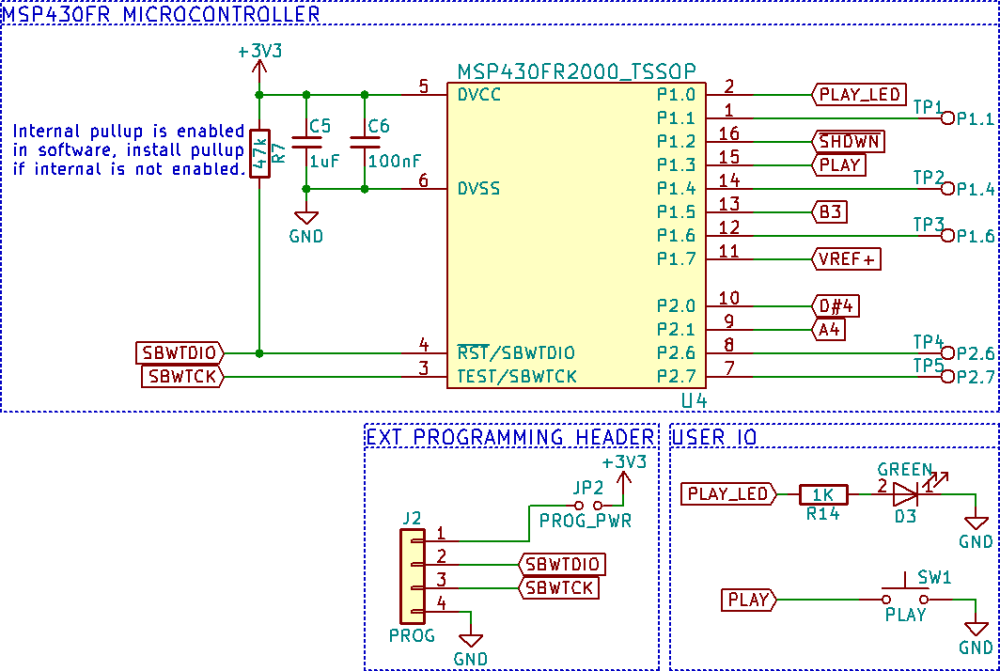
Schematic
Detailed Description
Sound Generation
The Leslie S-3L Locomotive Air Horn generates its distinctive sound using a three tone chord of approximately C, D#, and A (http://atsf.railfan.net/airhorns/s3l.html).
The onboard microcontroller generates the chord using three 50% duty cycle PWM signals. Since the MSP430FR2000 microcontroller has only one general purpose timer the method outlined in TI app note SLAA513A was implemented to generate multiple time bases on a single MSP430 timer module. This enables use of the lower cost MSP430FR2000 instead of having to move to a potentially higher cost MSP430 microcontroller with three separate timer modules.
Each PWM signal from the microcontroller is passed through a three stage RC low pass filter to produce a sine wave on the output. The RC low pass filter was designed with the help of the following online RC low pass filter calculator: http://sim.okawa-denshi.jp/en/CRtool.php
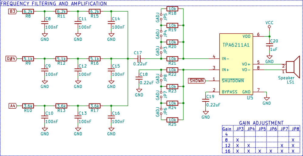
After each PWM signal is converted to a sine wave the signals are then mixed together before entering the audio amplifier. The audio amplifier is a TPA6211A1 mono audio power amplifier. The audio amplifier has 4 adjustable gain settings that can be changed by desoldering the smd jumpers (JP3 to JP6) as indicated by the table. For example to set a gain of eight JP4, JP5, JP6, and JP7 would be removed from the PCB. The amplifier can drive a 4-8Ω speaker.
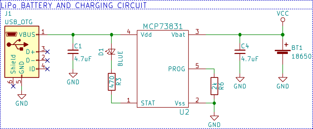
Battery Circuitry
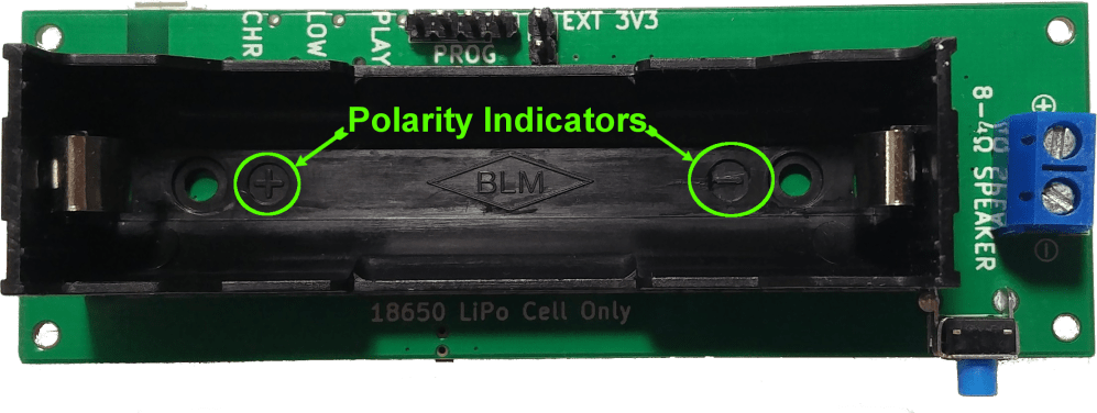
The circuit is powered with a standard 18650 LiPo cell. Be sure to observe polarity of the battery holder. The positive end of the battery installs opposite of the speaker terminal. Installing the battery in reverse polarity will destroy the battery charger IC and will damage the remaining circuitry. Don’t ask me how I know.
Charging is controlled by the MCP73831 charge management IC at a maximum charging current of 500mA using the micro USB port. This USB port if for charging only, the data lines are not connected to the MSP430FR2000 microcontroller. A blue LED indicator is turned on while the battery charges. The LED turns off to indicate that the battery is fully charged.
A red LED is used to indicate a low battery voltage. The MIC7221 comparator is used to illuminate the LED when the battery voltage drops below ~3.3V. The internal 1.2V reference from the microcontroller is used as the voltage reference for the comparator.
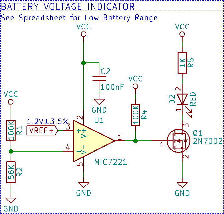
The onboard comparator of the MSP430FR2000 was not used due to issues with getting it to function correctly, most likely error on my part. To save time and frustration an external comparator was used instead.
The MSP430FR2000 microcontroller has a maximum voltage supply rating of 3.6V requiring a 3.3V low dropout regulator to prevent a fully charged LiPo cell voltage of 4.2V damaging the microcontroller. SMD JP1 can be desoldered from the circuit to put the LDO in shutdown mode, turning off the microcontroller.

Firmware
The microcontroller spends much of its time in a low power sleep mode, the full circuit draws about 0.3mA of quiescent current. A 1600mAh LiPo cell will have a standby life of over 3700 hours or 154 days!
Sound is generated when the user presses and holds down the play button. There are two play buttons on the PCB, a small SMD button and a friendlier medium sized right angle button. The PCB was originally designed to use only the SMD button but a last minute change added the right angle through hole button. Both are populated to allow multiple options of triggering sound generation. The green LED indicator is used to indicate when the sound is being generated.
Below is the code loaded onto the microcontroller. I have attempted to add descriptive comments for future me to understand. Hopefully it will allow others to understand as well.
This file contains hidden or bidirectional Unicode text that may be interpreted or compiled differently than what appears below. To review, open the file in an editor that reveals hidden Unicode characters.
Learn more about bidirectional Unicode characters
| //****************************************************************************** | |
| // MSP430FR2000 – Train Horn Hold To Play | |
| // | |
| // Description: Toggle pins at multiple frequencies using only TimerB, | |
| // mimic train horn for silly reasons. | |
| // P1.5 toggles using CRR0 and software. P2.0 and P2.1 toggle using CCR1 and CCR2 | |
| // Button on P1.1 enables frequency generation while held low | |
| // 1.2 VREF+ output on pin 1.7 to connect to external comparator for LiPo voltage monitor, | |
| // could not get MSP430 internal comparator to work | |
| // | |
| // ACLK = TBCLK = 32768Hz, MCLK = SMCLK = default DCODIV ~1MHz | |
| // P1.5 = CCR0 ~ 32KHz/(2*64) = ~256.00Hz -> target frequency: 255Hz (~C4) | |
| // P2.0 = CCR1 ~ 32KHz/(2*53) = ~309.13Hz -> target frequency: 311Hz (~D#4) | |
| // P2.1 = CCR2 ~ 32KHz/(2*37) = ~442.81Hz -> target frequency: 440Hz (A4) | |
| // | |
| // MSP430FR2000 | |
| // —————– | |
| // | P1.0|–> LED for timer status | |
| // | P1.2|–> Audio Amp Shutdown | |
| // | P1.3|<– Play Button to gnd | |
| // | | | |
| // | P1.7/VREF+|–> 1.2VREF Output | |
| // | | | |
| // | P1.5|–> ~248.24Hz | |
| // | P2.0/TB0.1|–> ~309.13Hz | |
| // | P2.1/TB0.2|–> ~442.81Hz | |
| // | | | |
| // | |
| // | |
| // TimerB multi frequency based on TI app note SLAA513A and accompanying code | |
| //****************************************************************************** | |
| #include <msp430.h> | |
| // Port1 Pin Defines | |
| #define PLAY_BTN BIT3 // Play button port 1 input | |
| #define PLAY_LED BIT0 // Play LED port 1 output | |
| #define AMP_EN BIT2 // Amplifier enable port 1 output | |
| int main(void) | |
| { | |
| WDTCTL = WDTPW | WDTHOLD; // Stop WDT | |
| // Configure reset | |
| SFRRPCR |= SYSRSTRE | SYSRSTUP; // Enable internal pullup resistor on reset pin | |
| // Configure Interrupt Button | |
| P1IES |= PLAY_BTN; // play button interrupts on high-to-low transition | |
| P1REN |= PLAY_BTN; // enable internal resistor | |
| P1OUT |= PLAY_BTN; // set resistor to pullup | |
| // Configure Audio Amp Shutdown | |
| P1DIR |= AMP_EN; // set as output | |
| P1OUT &= ~AMP_EN; // Pull low to turn off audio amp | |
| // Configure Play LED indicator | |
| P1DIR |= PLAY_LED; // set as output | |
| P1OUT &= ~PLAY_LED; // turn off LED | |
| // Configure Timer_B Outputs | |
| P2SEL0 |= BIT0 | BIT1; // Select TB0.1 and TB0.2 pin functions for P2.0 and P2.1 | |
| P2DIR |= BIT0 | BIT1; | |
| P1DIR |= BIT5; // P1.5 is an output | |
| // Configure Voltage Reference Output | |
| P1SEL0 |= BIT7; // Select VREF+ pin function for P1.7 | |
| P1SEL1 |= BIT7; | |
| // Configure Unused GPIO as outputs per ULP advice | |
| P1DIR |= BIT1 | BIT4 | BIT6; | |
| P2DIR |= BIT6 | BIT7; | |
| PM5CTL0 &= ~LOCKLPM5; // Disable the GPIO power-on default high-impedance mode to activate | |
| // previously configured port settings | |
| // Configure reference | |
| PMMCTL0_H = PMMPW_H; // Unlock the PMM registers | |
| PMMCTL2 |= EXTREFEN; // Enable external reference | |
| while(!(PMMCTL2 & REFGENRDY)); // Poll until internal reference settles | |
| P1IFG &= ~PLAY_BTN; // clear any pending interrupts | |
| P1IE |= PLAY_BTN; // enable interrupts on P1.1 | |
| // setup timerB | |
| TB0CCTL0 = OUTMOD_4 + CCIE; // TBCCR0 toggle, interrupt enabled | |
| TB0CCTL1 = OUTMOD_4 + CCIE; // TBCCR1 toggle, interrupt enabled | |
| TB0CCTL2 = OUTMOD_4 + CCIE; // TBCCR2 toggle, interrupt enabled | |
| TB0CTL = TBSSEL_1 | TBCLR | TBIE; // ACLK, clear TBR, enable interrupts | |
| TB0R = 0xFFFF; // Set initial count of Timer_B | |
| // removes pause before initial sound generation | |
| for(;;) { | |
| __bis_SR_register(LPM3_bits | GIE); // Enter LPM3, enable interrupts | |
| TB0CTL |= MC_2 | TBIE; // enable timer | |
| while (!(P1IN & PLAY_BTN)); // Poll until play button is released | |
| P1OUT ^= PLAY_LED | AMP_EN; // toggle play LED for status indicator | |
| // turn off audio amp | |
| TB0CTL &= ~MC_2; // disable Timer_B | |
| P1OUT &= ~(BIT5 | BIT6 | BIT7); // set pins low since they could have been high during interrupt | |
| // delay to prvent fast button presses from locking up system | |
| __delay_cycles(20000); | |
| // enable play button again | |
| P1IFG &= ~PLAY_BTN; // acknowledge all interrupts | |
| P1IE |= PLAY_BTN; // enable interrupt on play button | |
| } | |
| } | |
| // Port1 Interrupt Vector handler | |
| #pragma vector=PORT1_VECTOR | |
| __interrupt void PORT1_ISR(void) | |
| { | |
| P1IE &= ~PLAY_BTN; // disable any further interrupts | |
| P1OUT ^= PLAY_LED | AMP_EN; // toggle play LED for status indicator | |
| // toggle audio amp on | |
| __bic_SR_register_on_exit(LPM3_bits); // Exit LPM3 | |
| } | |
| // Timer0_B3 Interrupt Vector (TBIV) handler | |
| #pragma vector=TIMER0_B0_VECTOR | |
| __interrupt void TIMER0_B0_ISR(void) | |
| { | |
| TBCCR0 += 64; | |
| P1OUT ^= BIT5; // ~256Hz frequency generation on P1.5 | |
| } | |
| // Timer0_B3 Interrupt Vector (TBIV) handler | |
| #pragma vector=TIMER0_B1_VECTOR | |
| __interrupt void TIMER0_B1_ISR(void) | |
| { | |
| switch(__even_in_range(TB0IV,TB0IV_TBIFG)) | |
| { | |
| case TB0IV_NONE: | |
| break; // No interrupt | |
| case TB0IV_TBCCR1: // CCR1 | |
| TBCCR1 += 53; // ~309.13Hz frequency generation on P1.6 | |
| break; | |
| case TB0IV_TBCCR2: // CCR2 | |
| TBCCR2 += 37; // ~442.81Hz frequency generation on P1.7 | |
| break; | |
| case TB0IV_TBIFG: // overflow | |
| break; | |
| default: | |
| break; | |
| } | |
| } |
Get the code from the Github repository.
Modifications
“That’s cool and all but how do I modify the hardware/firmware.” – you
I suspect that very few if anyone would ever find a use for this exact project but it does offer some aspects that may be useful elsewhere with little to no modifications.
Generating a Different Chord
The MSP430FR2000 is capable of generating up to a 3 note chord, a limit set by Timer_B having only three capture and compare registers (CCRx). To generate other frequencies the following formula is used:
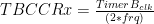
TBCCRx is the increment to write to the capture and compare register. TimerB_clk is the clock source for timer_b, which in my code is 32 kHz (binary 32 kHz which is 32,768 Hz).
The RC low pass filter will have to be tuned for the new frequency. Using the online calculator set the frequency and choose a standard capacitor value, something like 100nF which is widely available. The calculator will then suggest a resistance value for your filter. Filtering is not necessary but it does produce a nicer sound than a PWM wave.
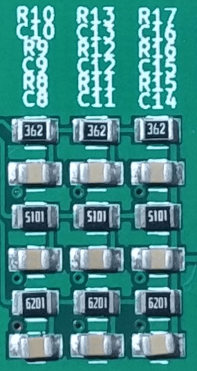
As an example if I wanted P2.1 to generate a 523 Hz frequency I would increment TBCCR2 31 by changing line 144 in the code above to TBCCR2 += 31. R10, R13, and R17 from the schematic would change to 3kΩ. For small changes in frequency from the original values you may be able to get away without modifying the RC filter. An oscilloscope will help determine if the output from the filter is close to a sine wave.
Changing Audio Amplifier Gain
Changing the gain to 12, 8, or 4 is possible by removing the corresponding jumpers according to the table on the schematic and the silkscreen. I chose these gain settings since they were the easiest to implement and worked well for my application. A gain higher than 16 will cause the audio signal to be clipped producing distorted sound.
Gains other than those from the table will require more effort. First remove all the jumpers along with resistors R18-R25.
R18-R21 is connected in parallel to pin 4 of the audio amplifier and R22-R25 is connected in parallel to pin 3 of the audio amplifier. The resistance value connected to pin 4 and pin 3 of the audio amplifier must be the same value.
Gain is calculated using the following equation:

For example if I wanted a gain of 10 I would make it so the R18-R21 resistors connected in parallel are equal to 4kΩ as well as the R22-R25 resistors connected in parallel.
A dual gang potentiometer can be connected instead of discrete resistors values but was not included in the final design due to the size of such potentiometers.
Uploading Firmware
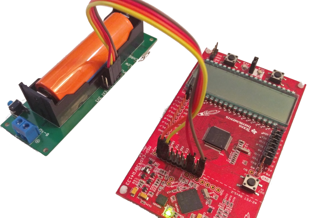
Firmware is uploaded to the MSP430FR2000 using the programming header and a MSP430 TI Launchpad. I used a MSP-EXP430FR4133 but other MSP430 Launchpads will work. Remove all the jumpers from the Launchpad eZ-FET header and connect to the programing header 3V3, GND, SBWTDIO, and SBWTCK. Do not connect 5V power from the Launchpad or damage will occur. If you have a LiPo battery installed make sure to remove the jumper from the EXT 3V3 header before connecting the launchpad. Code is compiled and uploading using Code Composer Studio 7.4.0.
Open CCS 7.4.0 to either a new workspace or a previously created workspace. Create a new CCS Project using File -> New -> CCS Project. Select the MSP430FR2000 as the target.
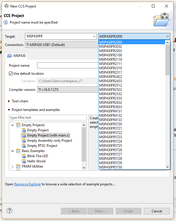
Chose a project name, I used train_horn_hold as my project name but anything will work. Select the Empty Project (with main.c) from the project templates and examples before clicking finish.
Replace the code in main.c with the code from my GitHub repository. Modify the code as you wish. To upload code click build (the hammer icon below Navigate) then click debug (the bug icon to the right of build). If the compiler returns with warnings you must fix these before you will be able to upload the code. The best place to search for help is TIs forums. Googling the error message will also yield useful help.
In the debug perspective click the play button to execute code. You can then see register settings, memory values, and more. This is my number one reason for abandoning the easy to use Arduino platform, debugging is amazing!
For more detailed help with CCS than I could ever give visit the CCS Wiki for a getting started guide or search YouTube for tutorials. The Embedded podcast also has a great blog series on getting started with the MSP430 microcontroller family with advice on how to setup and use CCS.
Application Specific Details
Below is a brief explanation of exactly why I built this device and the final product that this went into.
Why?
Have you ever made something only to ask yourself after it is finished, why? Me neither.
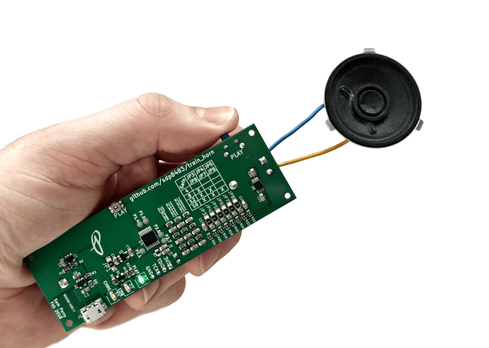
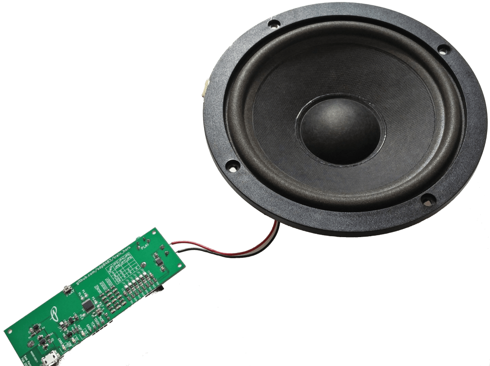
I needed to generate a jarring sound for a silly reason. This project started like many other projects with a trash find, a PA speaker that was just begging to be rescued and reused. Slowly this project evolved from a simple weekend or two Arduino based solution to the five week project presented above. Like many of my projects I used this particular one as a learning experience for programing and embedding a microcontroller from the MSP430 family of microcontrollers. In between the start and end of this project I also learned about sound generation using PWM and train horn chords.
After designing the schematic and PCB using KiCAD I sent the gerber files off for manufacture. The minimum order quantity was 5 but I found that ordering 10 PCBs cost the same amount as 5 so I have plenty of spares.
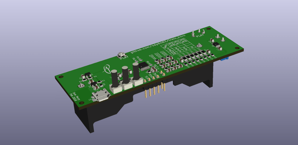
While the PCBs were being manufactured I exported a 3D model of the PCB from KiCAD for export into Fusion 360. From there I set to designing a 3D printable case to attach the PCB to the PA speaker I rescued from the dumpster. Being able to export a 3D model from KiCAD helped a lot with designing the case and made it super easy to have the design finished and printed before the PCBs arrived.
PCBs arrived within a week of ordering and I set about assembly. Having also ordered a solder paste stencil, populating the PCB took the most amount of time. I spent about half an hour populating the board, taking care not to mess up any of the resistor and capacitor values. Then it was into my reflow toaster oven for 6 minutes of anticipation. The battery holder, speaker terminal block, programing header, and right angle tactile switch was solder onto the PCB after reflowing the smd components. A quick firmware flash and it was time for the moment of truth. Success! Or more like choo-choo.
Ok, admittedly it does not sound exactly like a train horn but more of a horn in general. There is something else going on with the Leslie S-3L air horn then just the three chords, harmonics possibly? With that said this project is finally done, I accomplished my goal and learned a great deal about using the MSP430 microcontroller. Since I only needed one or two circuits I will list the remaining fully assembled circuits for sale on my Tindie store, just in case you too need to make some noise too.
The full schematic and design files are available in a GitHub repository: https://github.com/sdp8483/train_horn

