The Plan
Inspired in part by the Hex Game from The Ben Heck Show but with the simplicity of the Microsoft Calculator in programmer mode, this project aims to create a handheld/desktop calculator for converting between HEX, DEC, and BIN base numbers up to 16 bit. I find myself during times of programing always checking my number conversions with the MS calculator. I would prefer to have a physical calculator on my desk since I prefer the tactile feel over an on screen calculator.
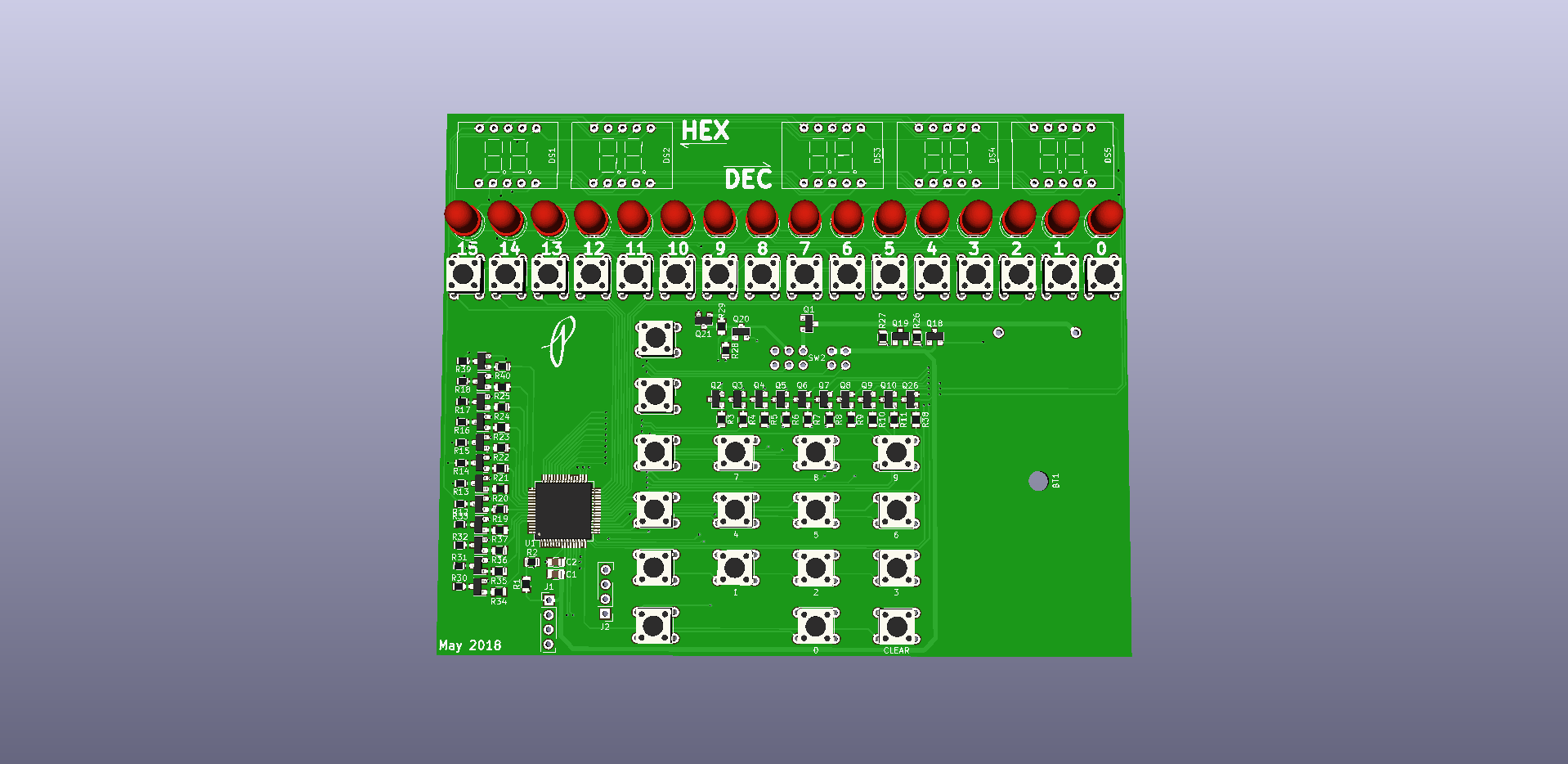
Base Convert will consist of a 8×8 matrix key input for numerals and characters A to F. There will also be 16 buttons for inputting binary values. This input arrangement will allow the user to input a number in any format. Three displays will be included to display the value input in hexadecimal, decimal, and binary all at once. Trying to get an old time calculator feel, the plan is to use 7-segment displays for HEX and DEC and a row of 16 LEDs for BIN. A MSP430 uC will run the calculator.
This device will convert the user input value in any of three number formats (HEX, DEC, and BIN) to the remaining number formats while displaying all formats at once. Input is accomplished by first selecting the number format using a selection switch (not pictured in preliminary render) and then using either the alphanumeric input pad or in the case of a binary number the tactile switches directly under the binary display. I want to keep this device simple with limited functionality; no games, internet connectivity, apps, ect. A stretch goal might to add some bit manipulation functions such as shifting and simple logic but that is only after the main goal is complete.
The end device will be small enough to be considered portable, the preliminary render is 106mm x 72mm but every effort will be made to make it smaller. It may end up being more of a desktop device than portable. I would prefer it to be battery powered, most likely alkaline batteries or possibly rechargeable LiPo.
In keeping with my 2018 goal of learning programming with the MSP430 line of microcontrollers this calculator will most likely use the MSP30FR4133 microcontroller since I have a launchpad and it is a low cost high pin count microcontroller. If this uC is not suitable for this project another MSP430 will be chosen. I plan to do most of the display and input in software relying very little on supporting ICs for display driving and user input but if it makes sense to use a specialized IC I will. The MSP430FR4133 has a built in LCD driver so it maybe possible and make better sense to switch to LCD displays for HEX and DEC output but I prefer 7-segment LED displays, they just look cool.
The Prototype
I have ordered a set of 5 PCBs so that I can start developing the firmware. I was going to breadboard everything but it was becoming a tangle of unmanageable wires with only 4 digits, 6 more along with 16 LEDs would be a monster. PCBs are so cheap and will save me the headache of wondering if my wiring of the breadboard is wrong so there is no reason for this project not to jump straight to a PCB.
I am not happy with how large I had to make the board and want to try to stick to the cheaper 100mm square PCB size or less in a future version.
I will have to abandon the 6mm tactile switches for the binary input to get the width down. If anyone has any suggestions for switches let me know. I was hoping to find illuminated ones but they are about the same size as the 6mm so no width savings. I may have to play around with not lining them up in a nice row, it bothers my love of straight lines but it may be necessary.
I also will have to see if having transistors to drive the LEDs (at least on the sink side) are necessary. If not then it could save a lot of wiring and components! Otherwise I will look into transistor arrays (ULN2003A?) or other options.
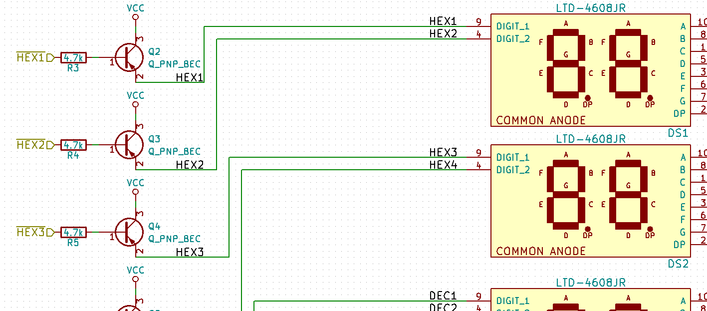
I like the 7 segment displays I have chosen, the LTD-4608JR 10mm 2 digit 7-segment display from LiteOn, they are super bright with very little current. I don’t see a reason why these will not be used in the final design.
Here is a render from KiCAD minus the components that I could not easily find 3D models for.
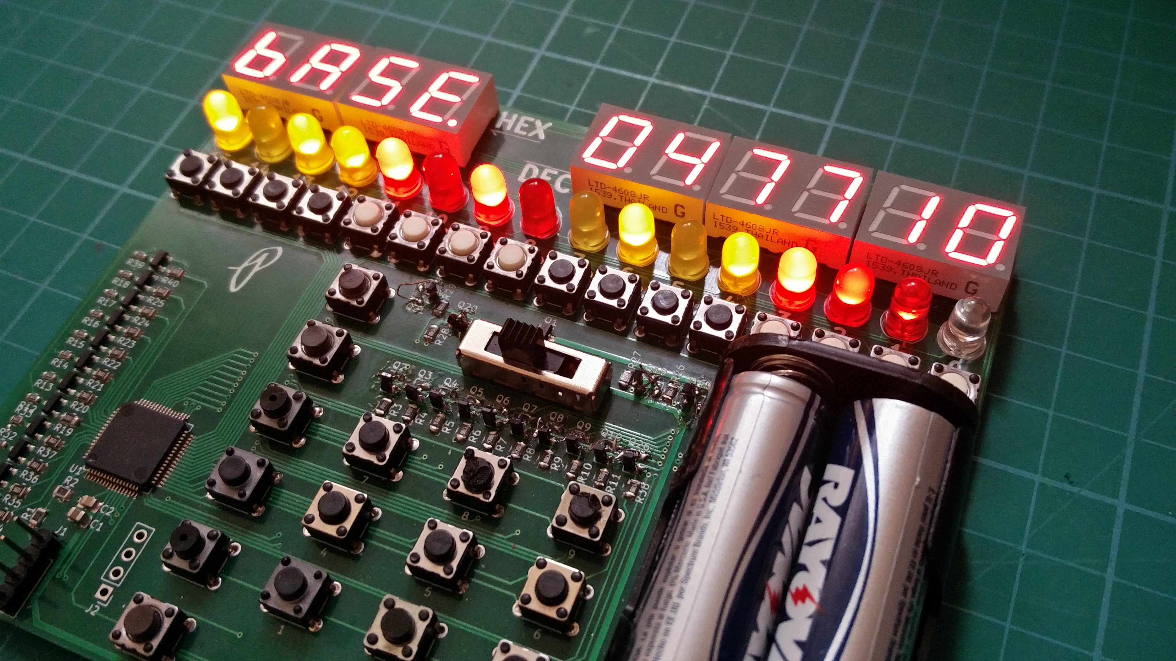
I finally got the boards assembled and have completed usable firmware that does more than just test out the display. I may be biased but I am liking what I created. The current firmware (available on GitHub if you want to see my inefficient coding skills) allows input of hexadecimal, decimal, and binary numbers using the keypad for the HEX/DEC and the buttons under the binary display for binary input. After finding some faulty tactile switches the inputs work very well considering the mess of code polling them. There is also a clear button along with an input mode selection switch that also acts as the power switch.
The Issues
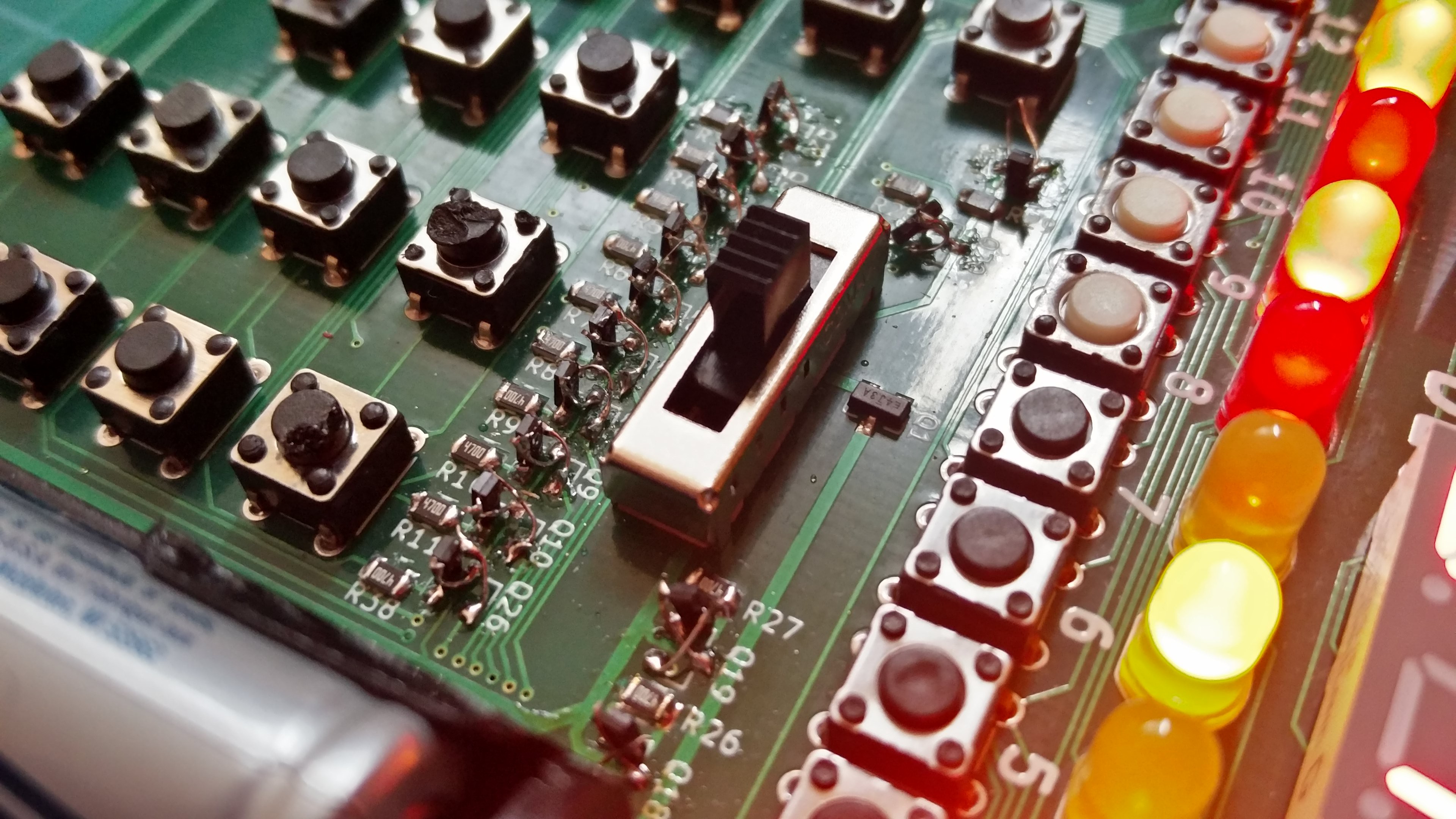
I ran into a few issues with the hardware and firmware that will have to be updated in the next PCB. For starters I must have completely forgot how to wire up a PNP transistor when capturing the schematic since I connected the collector to Vcc and not the emitter. This was the cause of a dim display that had me stumped for a few hours. I even dragged out my copies of The Art of Electronics 2nd and 3rd edition to read through the first few sections of the chapter about bipolar transistors and it was only after I sat down with pen and paper to see if I had chosen incorrect resistor values that I glanced at the PNP transistor hookup reminder on my trusty Adafruit PCB ruler that I noticed that I had wired them up wrong in the schematic. I searched on Digi-Key hoping to find SOT23 PNP transistors with BEC pinout with no luck. I ended up flipping the transistors on there ends and soldering thin magnet wire connections.
This will be fixed immediately and hopefully will be something I don’t forget to check not just for this project but for future ones.
Another major issue, but this one is not circuit breaking, is that I should have wired up the keypad to ports 1 and 2 only since they are the only ports on the MSP430FR4133 with interrupt capabilities. I wrongly assumed all pins could generate an interrupt but was soon proved wrong when Code Composer Studio when WTFLOL at my attempts to enable interrupts on ports 8 and 5.

Speaking of buttons I think the next revision will have the binary and keypad share the same pins. Maybe I can get fancy and disable the keypad not being used for the current input mode using external circuitry but I would not count on it. It may not be and issue if the bit0 button also inputs a 3 during hex/dec mode.
I also have some layout to fix so that it is easier to press the buttons. Why did I place the battery holder on the top where it can block access to buttons? I may also rethink the BIN display along with the input for the BIN display. Thouse 16 buttons take up a lot of space and make the board size unnecessarily wide. I was toying with using the keypad as input, ie key 9 would toggle bit9. I don’t know though, I like toggling the bits with the key right under them.
If anyone reading this knows of any PNP bipolar transistors in a SOT23 package where pins 1-3 are base, emitter, and collector respectively let me know. It would be nice to not have to throw away the 4 remaining prototype PCBs. I was able to replace all the PNP transistors with NPN transistors for a slightly dimmer but still usable display.
(I am lazy and this article is a copy paste from my project page on hackaday.io)
