Simulator is probably not a good word to use to describe this, naming is not something I am good at. I have been working on a project that uses a CR2032 coin cell and I would like to make current consumption measurements but connecting an external power supply is not easy. I came up with this way to easily connect my lab power supply to the project. I know there are ready made devices to do this such as the CR2032 Emulator (a more appropriate name) but I wanted something today as in right now. Using nothing more then some single sided copper clad PCB and my 3018 Pro CNC router I was able to make a CR2032 Simulator within an hour (counting 3D modeling and CAM).


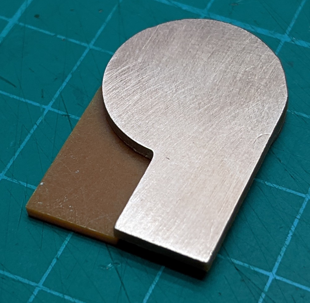
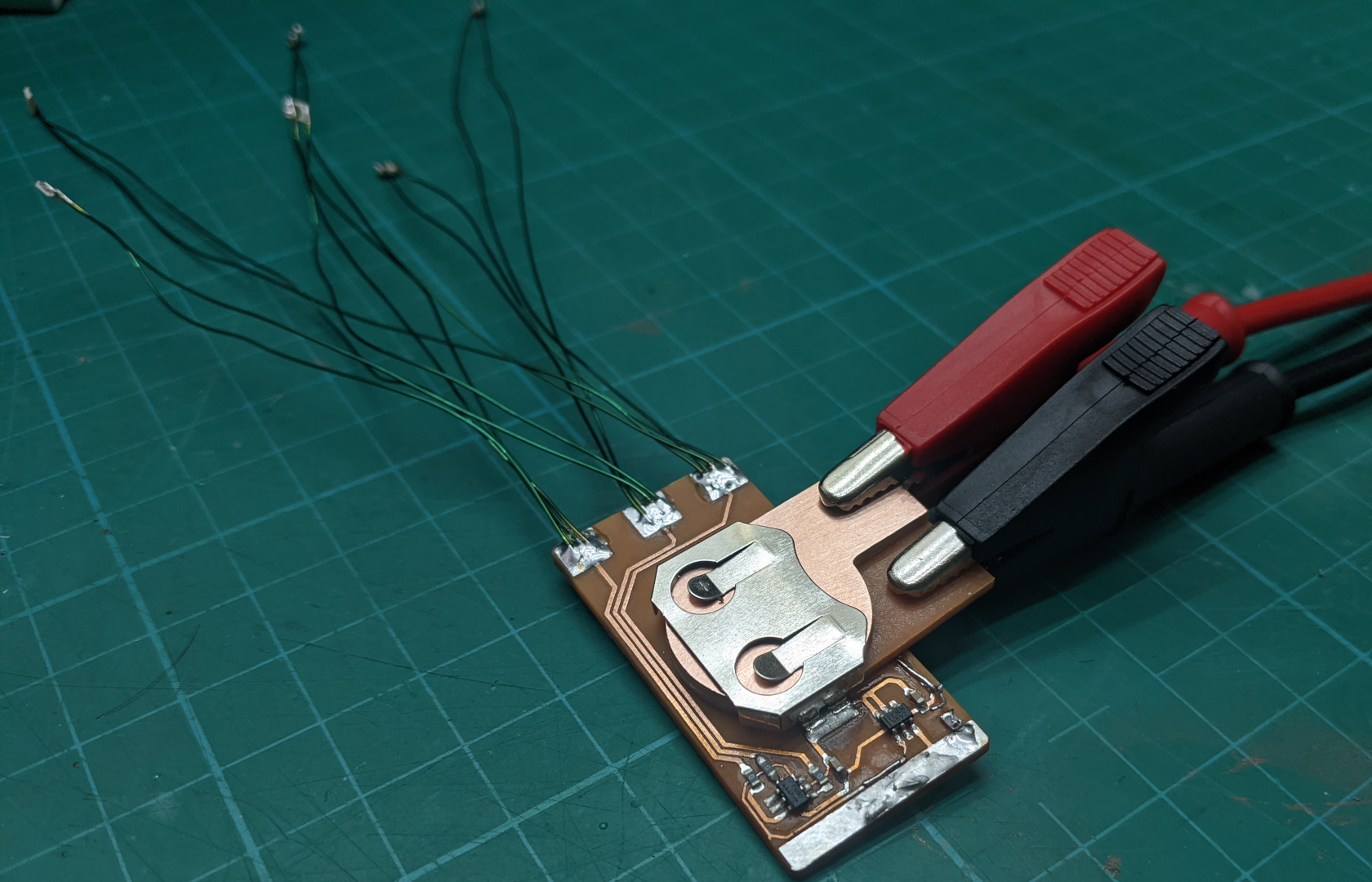
If you want to make your own just cut out two of the shapes from the sketch above using a CNC router. Use 1.6mm thick single sided copper clad PCB. Clean them up to remove any rough edges. Assemble them together back to back as shown above using double sided tape or glue. To use insert it into the CR2032 battery holder as show. Make sure you don’t short to any traces near the battery holder and observe the correct polarity when connecting to your power supply.
Not knowing your CNC router’s capabilities I would suggest drawing this up in your favorite CAD/CAM program and generating the GCODE to suit your machine but if you want to see the design files I used here they are:
