In a previous project for work I used a 18650 Battery Shield as a quick and easy way to add a battery to a semi portable controller. These shields were readily available and reasonably priced from Amazon allowing for quick shipping. Below is a photo of the shield that I used in my design:
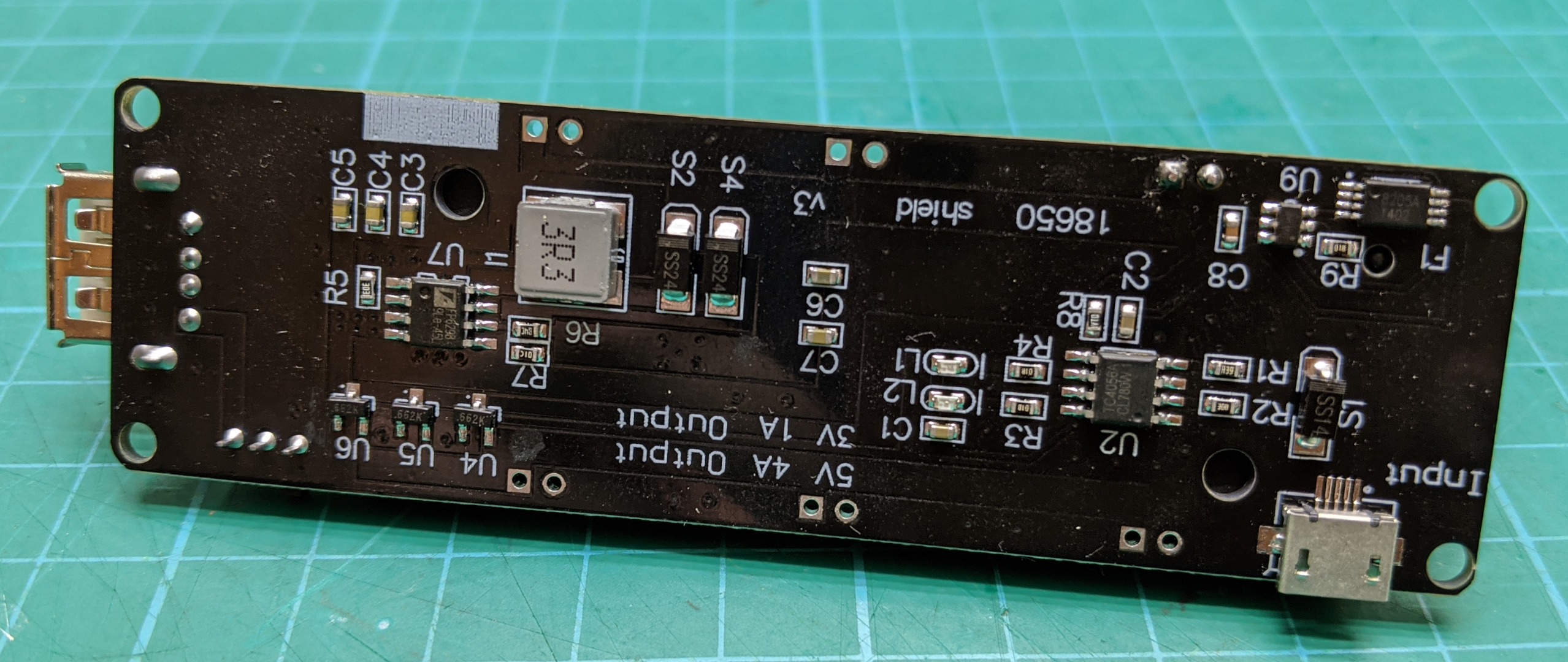
Now 9 months later I need to make up more controllers so I ordered more of the same 18650 battery shields from Amazon not thinking I would have any problems since the product image looked exactly like what I needed. I was wrong and instead received the “updated” version. Looking around it seems like it is very difficult to get the version I wanted shipped within a reasonable time frame.
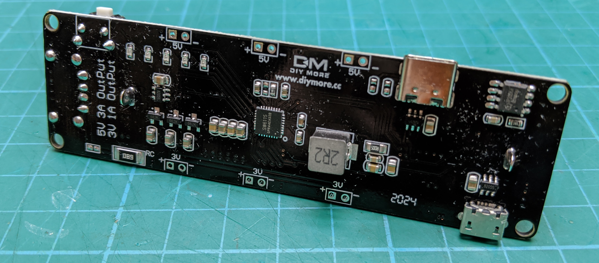
There are a few differences between the two versions. The first difference is the pin header spacing and placement on the edges has changed. Not a problem since this will be going into a 3D printed case and I can use wires to connect it to the controller. Not exactly plug in and easy to assemble anymore but not worth the hassle of trying to source the original shield. The annoying difference is that on the old version the 5V rail was on all the time but the new version the user needs to press the button on the side to turn on the 5V rail and then it will only stay on if there is a load connected to the rail. This is an issue since the shield will be buried in a 3D printed enclosure with no way for the user to get to the switch. To solve this problem I designed the following circuit that ‘presses’ the switch if the 5V rail turns off.
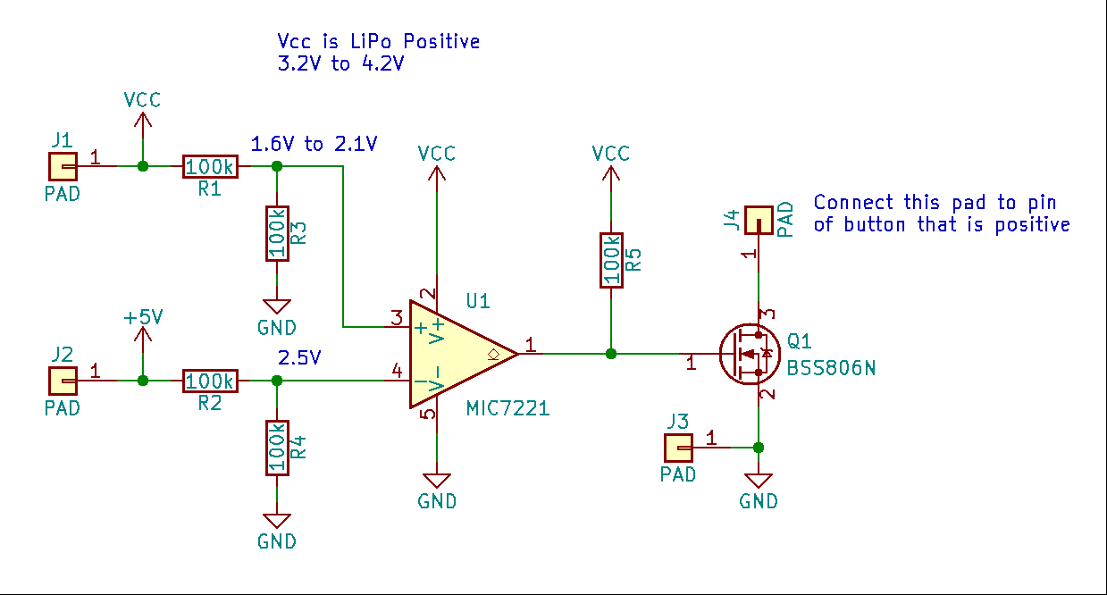
Comparator U1 looks at the voltage on the 5V rail and the 3V3 rail. If the 5V rail voltage is lower then the 3V3 rail then the button needs to be pressed so the comparator output goes high which drives the N-channel MOSFET Q1. The pin of the tactile switch which has a voltage above ground is connected to the drain of the MOSFET so when the MOSFET is turned on it connects this trace to ground just like if the user was to press the tactile switch. The inputs to the comparators go through a divide by two voltage divider so that the input to the comparator never exceeds Vcc. The 3V3 rail is always on and the comparator is powered directly by the LiPo.
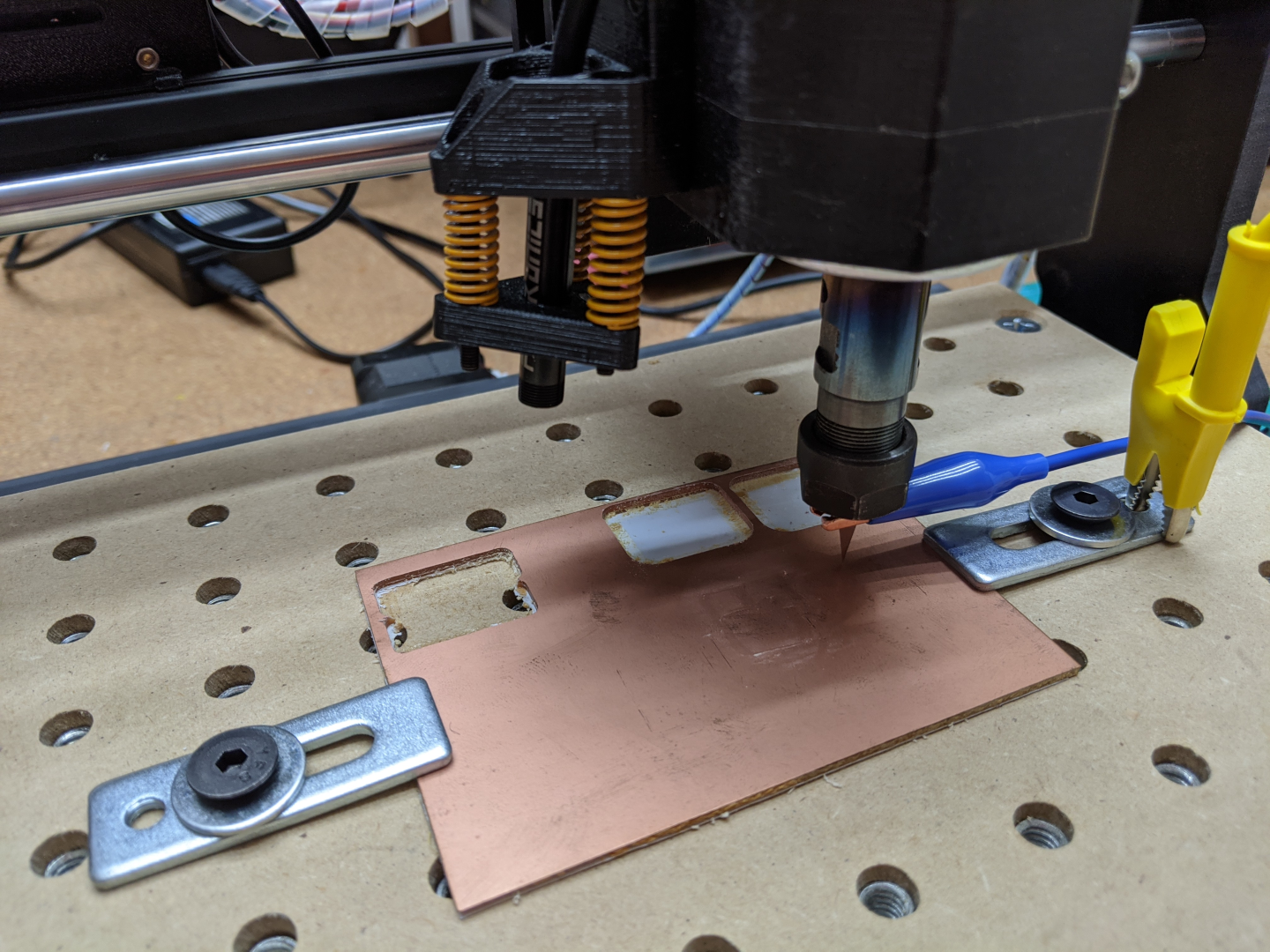
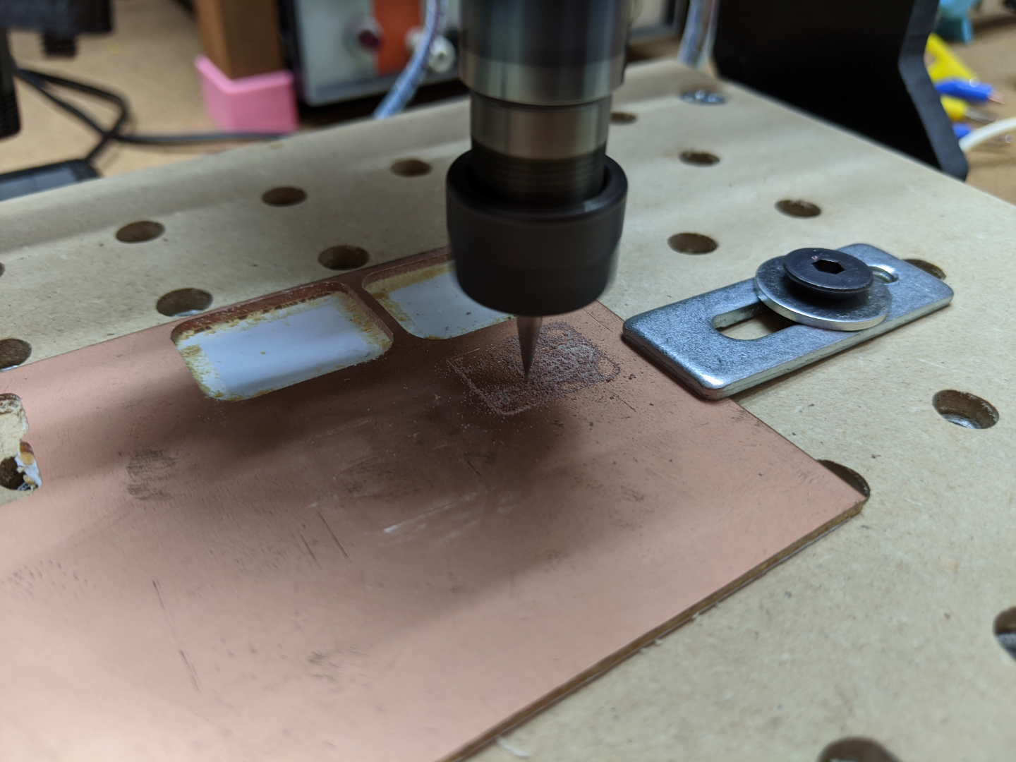
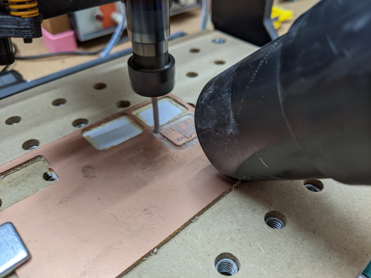
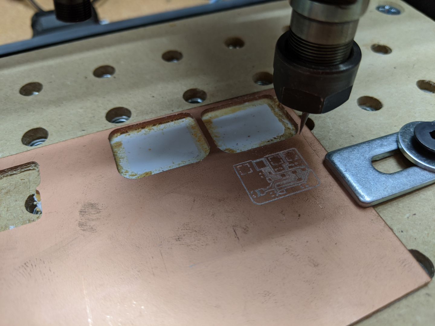
Wanting to get some experience milling PCBs with my CNC 3018 Pro Router I decided to manufacture these PCBs at home rather then send them out to a board house. The process was super easy and produced great results as shown in the photos below. Cutting the PCB to size has always been an area I struggle when making PCBs at home and I was super happy with how easy it was to use the mill to cut out the PCB shape. I will be using this technique for many future projects where I need only a handful of PCBs. I’m not going to go over the steps for milling a PCB here but for anyone interested here is an excellent forum post / tutorial that I followed: Milling PCBs with Cheap Chinese Desktop CNC Router.
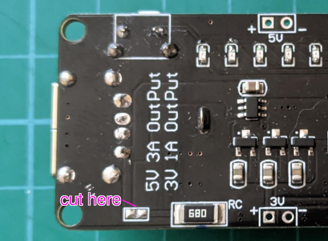
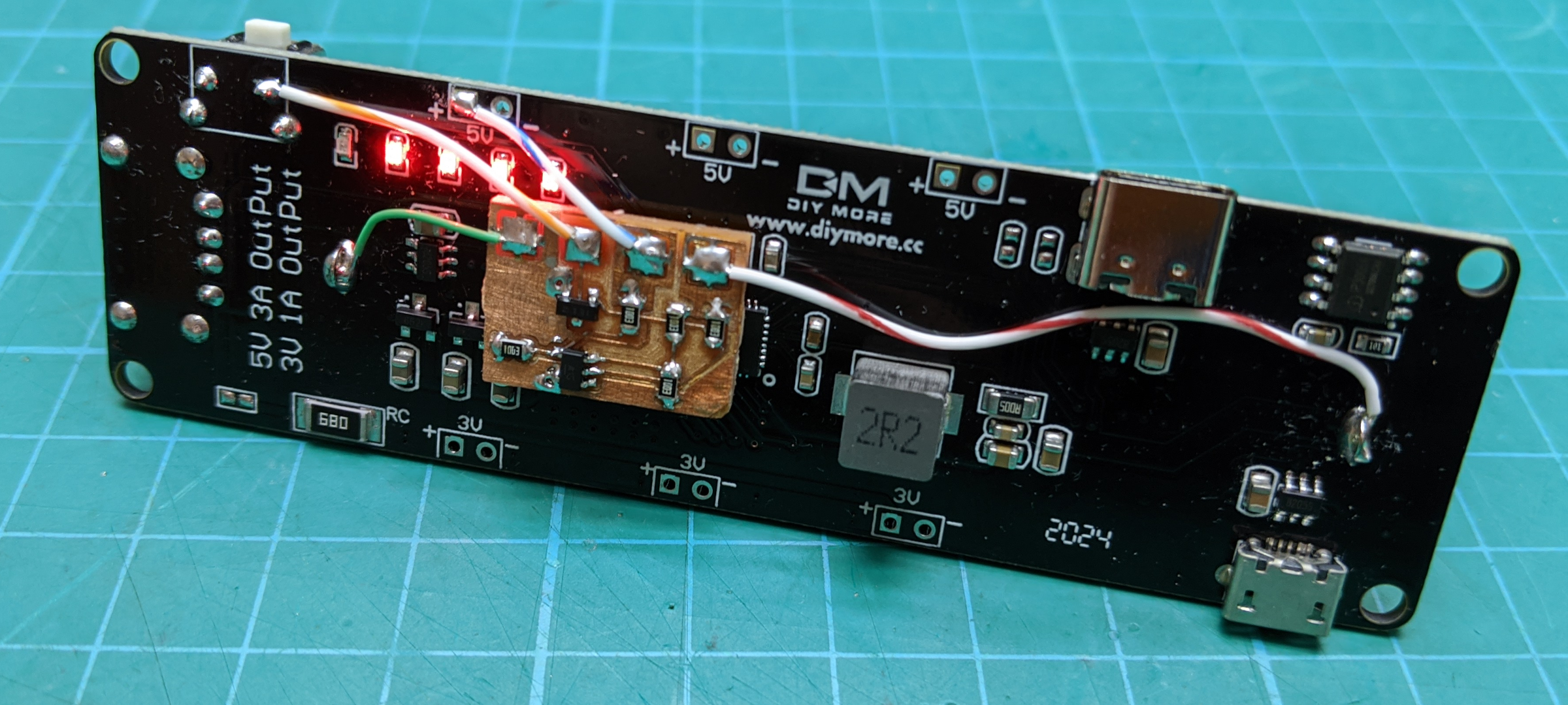
After populating the PCB with all the necessary components I used a drop of hot glue to attach it to the battery shield and then connected it up using multi-strand wire. Now the 5V rail stays on with no load. The only issue I can see is a major hit to battery life since without a load the shield draws about 100mA. Reducing this current is easy and not something that I discovered until later. There is a large surface mount resistor on the edge with the 3V connections, see the photo below. Next to this is a unpopulated footprint for what looks like a 0805 resistor, this is a solder bridge. Cut the trace between the two solder pads and the current will go down to a few milliamps.
I have uploaded the design files to a GitHub repository for anyone interested: 18650_keep_alive.

Hello! I saw your post on the Arduino forum and checked your video (great work!). I had also used an older v3 version (single battery) for an interactive art project which needed to be wireless and enclosed within its shell. Because it was a prototype, I was able to swap the batteries when they died. The prototype used an ESP8266, an IMU, logic level converter and an LED strip (ws2812b), as such I was running some things at 3.3V and some at 5V.
I’m now working on v2 of that project, and was looking into getting instead a V8 (double 18650 battery) to run the system for longer periods of time without charging, but have run into the same issues everyone else has (power cut-off, it wouldn’t stop charging, etc).
I also wanted to add a magnetic USB connector to the shell, so it could be set on a pedestal with the other magnetic connector (permanently hooked up to a power supply). That way, when people would use the shell, it would run off the battery shield, and when put back on its pedestal, the magnetic connection would charge the battery as needed.
After reading blog posts, forums and watching many videos (yours, Andreas Spiess’, etc) I’m convinced using these 18650 shields will not satisfy the requirements and may indeed be dangerous (since I can’t use the single battery shield fix from your post).
While doing some more looking on AliExpress I stumbled into these boards (I’ll be ordering a couple to test), and wanted to ask if you’ve tried them at all?
Double battery (5V output): https://www.aliexpress.com/item/3256805009119745.html
Single battery (5V output): https://www.aliexpress.us/item/2251832819253612.html
Cheers and keep up the great work!
LikeLike
Hello and thanks for your comment.
I have not tried the boards you have linked to. I have given up on using these types of 18650 boards in projects as they are unreliable for me and I don’t have the control over their design and operation I would like, especially in projects for work. Having said that those boards you have linked look interesting, I particularly like the ability to output voltages higher then 5V. I guess that is a nice advantage of them going to USB C.
I would be interested in a link to the Arduino forum post as I was not aware of it.
Your project sounds interesting and a fun design challenge. Best of luck on it!
LikeLike
Not a problem, I think I was confused then (seeing how I was doing this research around 2-3am). This is the link to the Arduino forum post:
https://forum.arduino.cc/t/load-sharing-mod-for-the-18650-battery-shield-v3/658135
LikeLike