Initially when using my CNC 3018 Pro Router for PCB milling I was in the habit of leaving one end of the touch probe connected to the spindle motor housing and the other end connected to the copper PCB blank being milled. This way I would never forget to connect up the probe while probing the tool height. I noticed a few months ago while the router was milling a PCB that it seems like there was an electrical arc or static discharge between the tool bit and the copper board. This got me worried about damaging the controller board since this probe is directly connected to the microcontroller.
To solve this problem once and for all I set about making an isolated probe for my CNC 3018 Pro Router. Isolating the probe protects the controller from high voltage shocks due to static discharge and voltage generated from the spindle motor. For this article I attempted to get a photo or video of the discharge that I was seeing that got me worried but I was unable to recreate it. It is possible that the arching I was seeing only happens in certain situations or I was mistaken and it didn’t actually happen and was only light reflecting off the spinning tool bit. Either way an isolated probe will help alleviate my worries and is something that should have been on the controller to begin with.
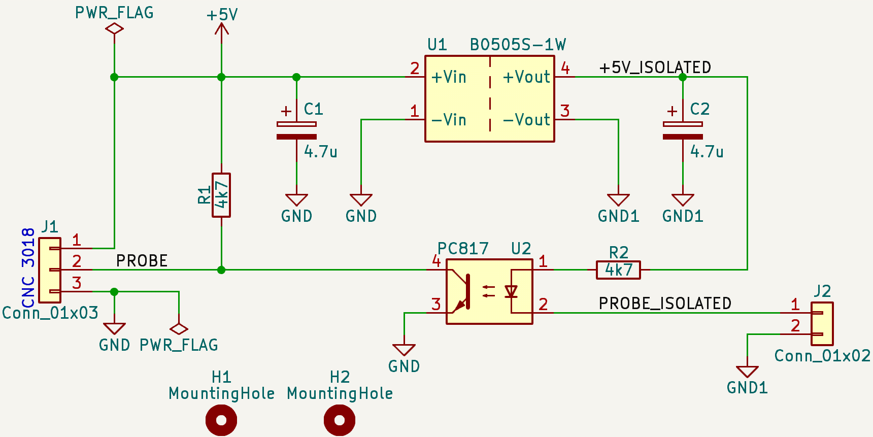
Isolated Probe Schematic
Isolation is achieved using a DCDC isolated power module and an opto-isolator. The B0505S-1W was used as the isolated power module. It accepts 4.5V to 5.5V input and outputs 5V with up to 200mA of current. This is more then enough current, the absolute maximum current for the LED in the PC817 is 50mA. I found the B0505S-1W on AliExpress but it can also be found on LCSC or an equivalent part from Traco Power, the TME 0505S, can be found on DigiKey. For the opto-isolator I used a equivalent part number to the PC817 that was in my junk bin. The exact part is not critical but it needs to be a NPN transistor output type.
Circuit Function
The circuit’s function is simple and nothing ground breaking. 5V from the CNC controller board is connected to pin 1 of J1 and ground is connected to pin 3. The B0505S-1W provides an isolated 5V rail for the probe. This module isolates both the ground and the 5V rail up to 1kV. One of the pins on J2 is connected to the tool bit and the other pin is connected to the blank copper PCB being milled. When the circuit is completed current can flow and the LED in the opto-isolator emits IR that then activates the photo transistor. The collector of this transistor is pulled up to the 5V rail on the CNC controller and when the transistor is turned on PROBE is pulled low. R1 may not be necessary as the internal pullup on the probe pin in the microcontroller is enabled.
Milled PCB
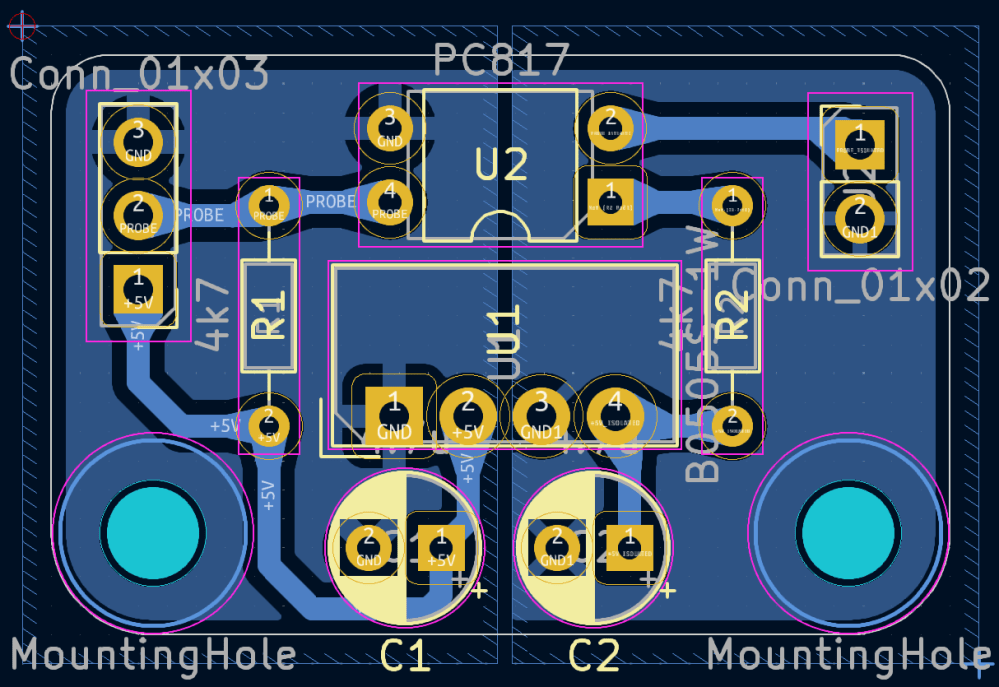
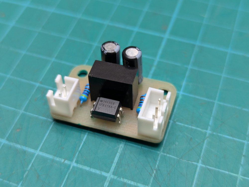

The PCB was designed to be milled out using the very same CNC 3018 router it will be installed on. I have been experimenting with UV curable soldermask so I used this PCB as an opportunity to apply such a soldermask. It turned out good looking and will help prevent the copper from oxidizing as the board ages. All components used were through hole parts to make layout as a single sided board easier. I used JST XH style connectors for connecting wires to the isolation PCB.
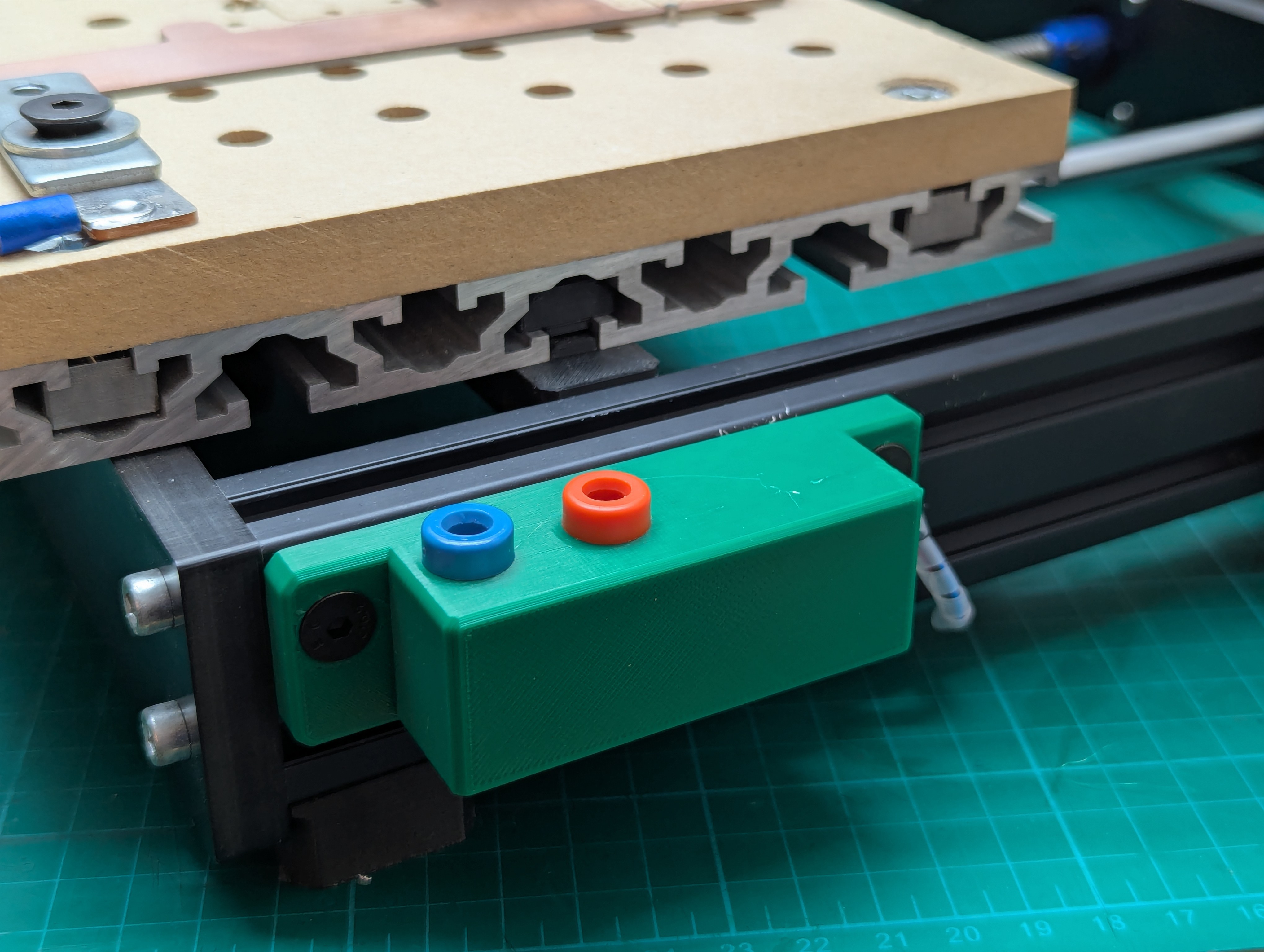
Case and Mounting
I designed a case to house the isolation PCB and the banana jacks for the probe connections. This will mount to the extruded aluminum on the right side of the CNC 3018 router. I was unable to figure out how to design this case so that it would not need to be printed with supports so for this model supports are needed only on the mounting holes for the PCB. In Prusa Slicer I used the paint on supports feature to add supports to only these mounting holes as the remainder of the case can be printed using bridging.
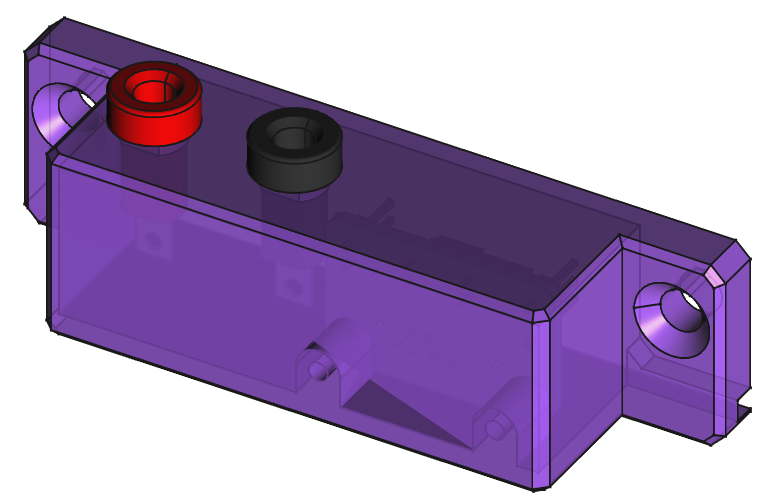


The PCB is mounted in the case using M3 screws. I dug in my junk bin of screws and found something that would work. The screws only need to be about 5mm long and cannot be much longer then 8mm. The banana jacks are reused from the non-isolated probe I previously had installed. These jacks are similar to Cinch Connectivity Solutions part numbers 108-0902-001 (red) and 108-0903-001 (black).
Installation

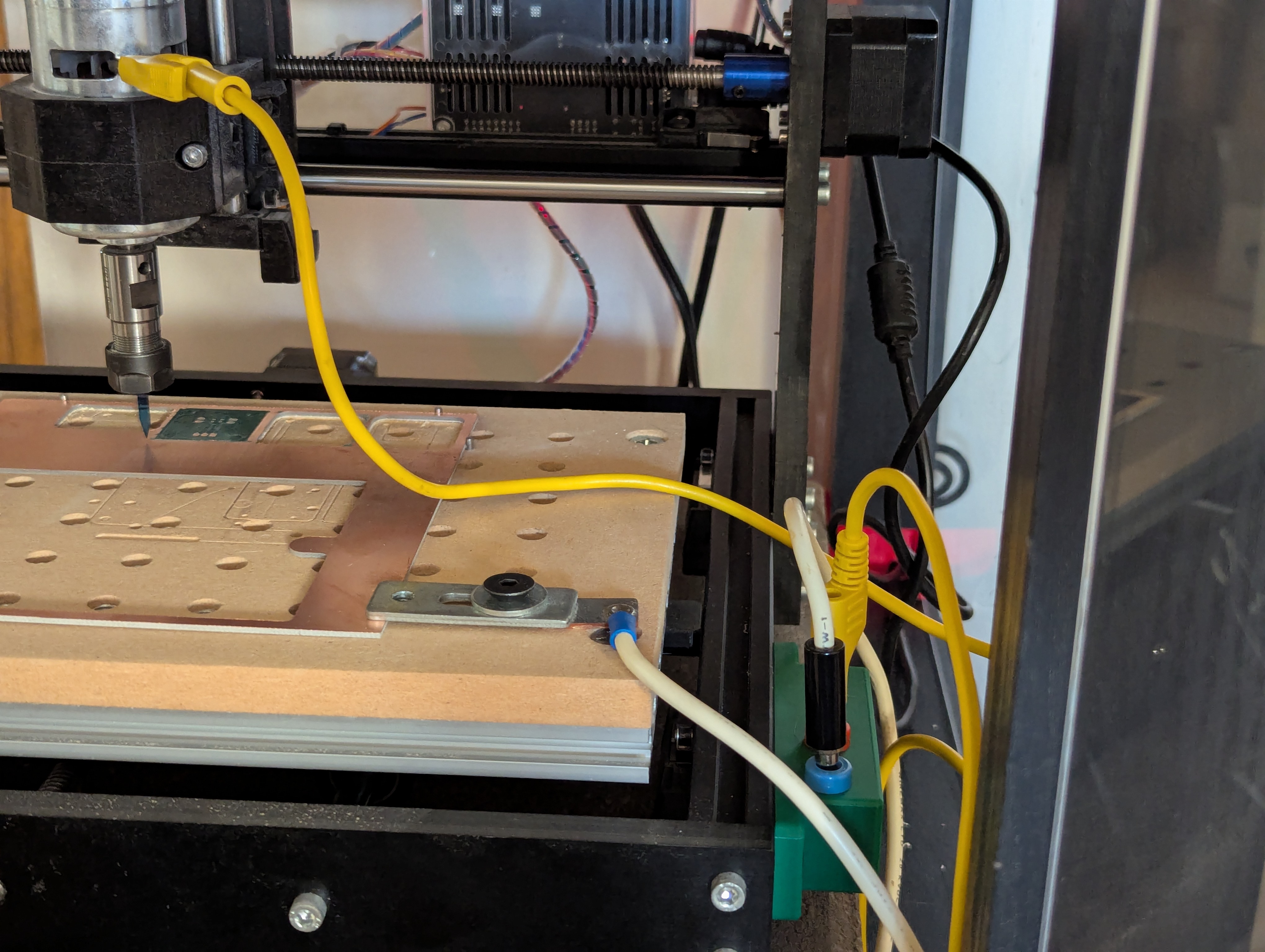
The wires to the isolation PCB could be soldered directly but I like being able to easily disconnect them. I connected up the short wires from the banana jacks to the isolation PCB first. I then made an extra long wire harness for connection from the isolation PCB to the CNC controller board. I bolted the case to the right side of the CNC 3018 router using M5 bolts and t-nuts. The wires were then cable tied to the frame of the CNC 3018 router. I cannot find the print files I used for the printed cable clips and tie points but searching on Printables for 2020 cable clip shows lots of similar options.


The bottom right pin header on the controller PCB is where the isolated probe will plug into. There is a silkscreen label that can be found below this pin header. The left most column of pins are 5V on the top row and ground on the bottom row. The next column of pins are the probe input pin on the top row, labeled A5, and again ground on the bottom row. Be sure to connect the 5V, PROBE, and ground from the isolation PCB to the correct pin positions. I go into wiring up to the Woodpecker V3.4 and cable management a little bit more in a previous article about adding endstops.
I was sure to test the isolated probe was properly installed by touching leads from the two banana jacks together and observing the response using the CNC command sender bCNC.
All design files can be found in a GitHub repository. The file for 3D printing the mounting case can also be found on Printables.

Hi Sam,
Your detailed guides and hands-on approach you share is truly helpful for electronic hobbyists, demonstrating your talent and expertise.
I’m Emily from PCBWay, a global provider of PCB and CNC services. I’d love to sponsor your project with our services.
A brief review would be greatly appreciated in return.
Would you be open to discussing? Looking forward to your reply.
Best regards,
Emily
Email: marketing@pcbway.com
LikeLike