After finding an old style desk telephone in the trash at work I decided to use it in an office prank, the phone that shouldn’t ring but does. The goal, modify the phone so that it will ring without any connection to the phone line. The stretch goal was to also have a message play on the handset when it is answered, maybe a creepy voice or loud breathing. Now to modify the phone.

Taking apart the phone I found a mess of wire, the circuit board for the keypad with a message LED, a mechanical ringer, and the phone hook. Knowing that I was mainly interested in the ringer and phone hook I proceeded to remove the mess of wire and other useless items. Oops, mistake number one; I cut the wires to the jack for the handset. After messing around soldering on new wires I discovered the reason this phone had been thrown out, the cord was broken and would intermittently disconnect when moved. The stretch goal was then abandoned and this project got a lot easier.
In my zeal to clean up the unused wires and connections I took apart the switch for the hook and removed the terminals I wouldn’t need. Mistake number two, I couldn’t get the switch back together. I don’t have a picture of the original but it was a stack of metal sheets with insolation between them and then connectors to the hook mechanism hooked to the flux capacitor which runs the photon generator… Needless to say it would have taken too long to put back together, instead I went with a small limit switch hot glued to the hook. Removing this switch worked out in the end as I was able to free up a large area for the 11.1V LiPo battery that will power this phone.
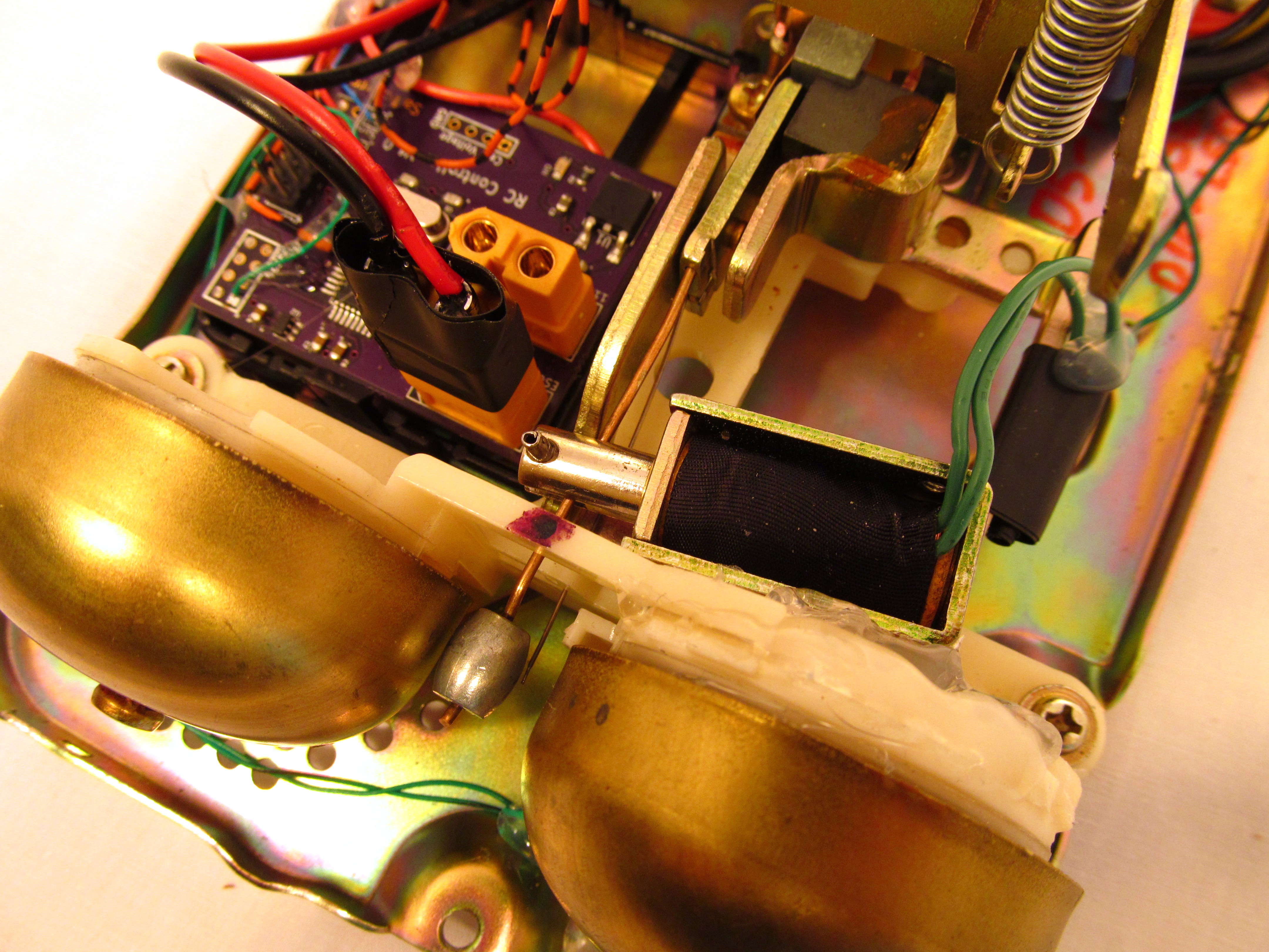
With everything cleaned up inside I set out determining the best method of controlling the ringer. A little bit of research reveled that the ringer is typical activated by a 20Hz AC wave. The ringer contains a electromagnet to move the striker between the two bells. I should be able to use a DC pulse to control it. After connecting it to my adjustable power supply I found that the ringer activates at about 30VDC. If I could get that voltage I will then be able to use a MOSFET to switch the current on an off to creating the ringing. Unfortunately I don’t have any batteries that work at that voltage and building a boost converter was beyond my ambition for this project, I needed something easy and quick. In one of my junk bins of parts I had a 12VDC solenoid which conveniently had a clevis on the plunger making it easy to hook up to the ringer. I removed the original coil and hot glued this solenoid in its place. I threw together a free formed MOSFET circuit with a op-amp set to a gain of 2 to drive the gate. Don’t forget the protection diodes for when the solenoid switches off, that voltage spike will eventually kill the MOSFET. Now I could easily control the ringer and do so at a voltage much lower then the original. The solenoid will even work at voltages lower then 12VDC, the pull in force will just be reduced.
For controls I went with the tried and true Arduino, the first setup used an actual Arduino Uno board. Since I wanted to make this more permanent I used a circuit board I had designed myself for a failed project. This is exactly the same as the Arduino, it uses the SMD version of the ATMEGA328P but doesn’t include the USB connector. Instead a ISCP header is used for programing. The benefit of using this is that I don’t have to tie up one of my Arduino Uno’s in a project and it is much cheaper, less then $10.
For power I used a 11.1VDC LiPo battery that is used in RC cars. This was also from the same failed project as the controller board (I was going to build an RC air boat if you were curious). Now I just needed to button everything up nice, the battery fit in the place where the hook switch was previously located, good thing I couldn’t get it back together. I was able to hot glue the controller board in the same place that the main PCB was previously, this allowed me to use the plastic holder as insulation from the metal base. The solenoid was already in place and the MOSFET with op-amp was hot glued in a convenient place under the keypad, out of the way from the battery. Not the most efficient heat sink for the MOSFET but it wouldn’t be running enough to heat up.
|
|
|
|


Now for the code. I wanted the phone to behave as closely to possible as a normal phone. My first task was to get the ringer sound just right. I played around a lot with a function generator and my ringer/solenoid/MOSFET circuit and found that a frequency of 20Hz was close to the sound I wanted. I also played around with how long it will ring and the pause between rings. I found that 20 rings was a good ring length with a one second delay between the next 20 rings. After this I opened up the Arduino IDE and went for it.
I uploaded the code and tested it out. Partial success on the first try! It rang after the set time while the phone was on the hook and stopped when the phone was picked up. Unfortunately some poor coding wouldn’t allow it to ring again after being hung up. I wrote out a quick outline, see it below, of how the phone should operate at every point and was able to create code that would allow the phone to ring after being hung up.
Phone Operation Outline
- Power On
- Presets
- Pins
- Hook
- Ringer
- LED
- Constants
- RingLength
- WaitMin
- WaitMax
- Pins
- Setup
- Pinmode
- Loop
- Phone on hook?
- Yes – Continue
- No – delay 10ms then retry
- Get random number WaitToRing
- WaitMin < WaitToRing < WaitMax
- Save current millis()
- Wait to ring
- Check if phone is on hook
- no – return to loop start
- yes – continue waiting
- Check if phone is on hook
- Ring
- Ring for RingLength
- Check if phone is on hook
- No – return to loop start
- Yes – continue ringing
- Is RingLenght up?
- No – continue ringing
- Yes – turn on LED
- Check if phone is on hook
- Wait period
- Return to Loop
- Ring for RingLength
- Phone on hook?
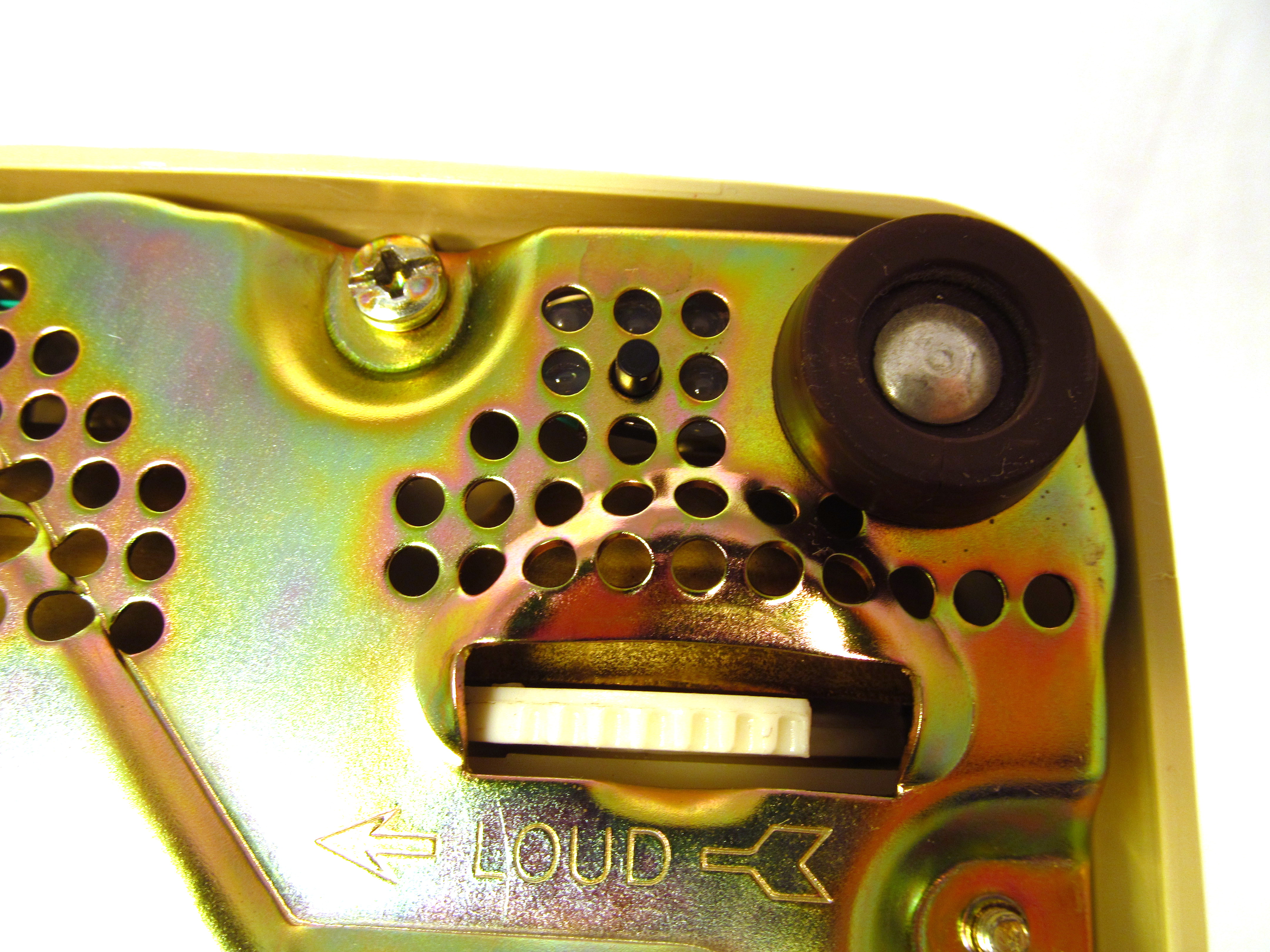
Before calling this project finished I decided it would be useful to have a reset switch for the ATMEGA328P and a power switch so that I could shut the phone off. These were hacked into the existing circuitry and hot glued so that the holes on the phone base allow discrete access.
|
|
|
|


The code is below. Just copy and paste into the Arduino IDE. I used version 1.6.0 when I wrote this.
//The Phone That Shouldn't Ring - An Office Prank
//Samuel Perry
//March 2015

//http://www.samueldperry.com
//Feel free to modify and reuse any of my code.

const int hook = 5;  //phone hook on pin 5
const int bell = 9;  //ringer on pin 9
const int led = 10;  //flashing led on pin 10

const long ring_length = 30000;  //ring for 30 seconds
const long waitmin = 15000;  //wait to ring in ms, min for random function
const long waitmax = 60000;  //wait to ring in ms, max for random function

long wait_to_ring;
long wait_start;
long ring_start;

boolean dont_ring;

void setup() {
  pinMode( hook, INPUT_PULLUP );
  pinMode( bell, OUTPUT );
  pinMode( led, OUTPUT );
}

void loop() {

  while( digitalRead( hook ) != HIGH ) {
    wait_to_ring = random( waitmin, waitmax );
    dont_ring = false;
    wait_start = millis();

    while( millis() - wait_start < wait_to_ring && dont_ring == false ) {
      if( digitalRead( hook ) == HIGH ) {
        dont_ring = true;
      }else{
        delay(1);
      }
    }

    if( dont_ring == true) {
      break;
    }

    ring_start = millis();
    while( millis() - ring_start < ring_length && dont_ring == false ) {
      for( int dings = 1; dings < 21; dings++ ) {
        digitalWrite( bell, HIGH );
        delay( 20 );
        digitalWrite( bell, LOW );
        delay( 30 );
        if ( digitalRead( hook ) == HIGH ) {
          dont_ring = true;
          break;
        }
      }
      delay( 1000 );
    }

    if( dont_ring == true ) {
      break;
    }else{
      delay( 100 );
      digitalWrite( led, HIGH );  //Blinky LED will blink without toggling pin
    }
  }
}
Feel free to modify, steal, or reuse any part of it. If you have suggestions to make it better let me know.
