The Breadboard Power Jumper connects the edge rails (bus strips) of a standard solderless breadboard together while also providing clip points for power leads. This design was heavily influenced by a design from IMSAI Guy with slight modifications to the PCB shape and the addition of manufactured test points.
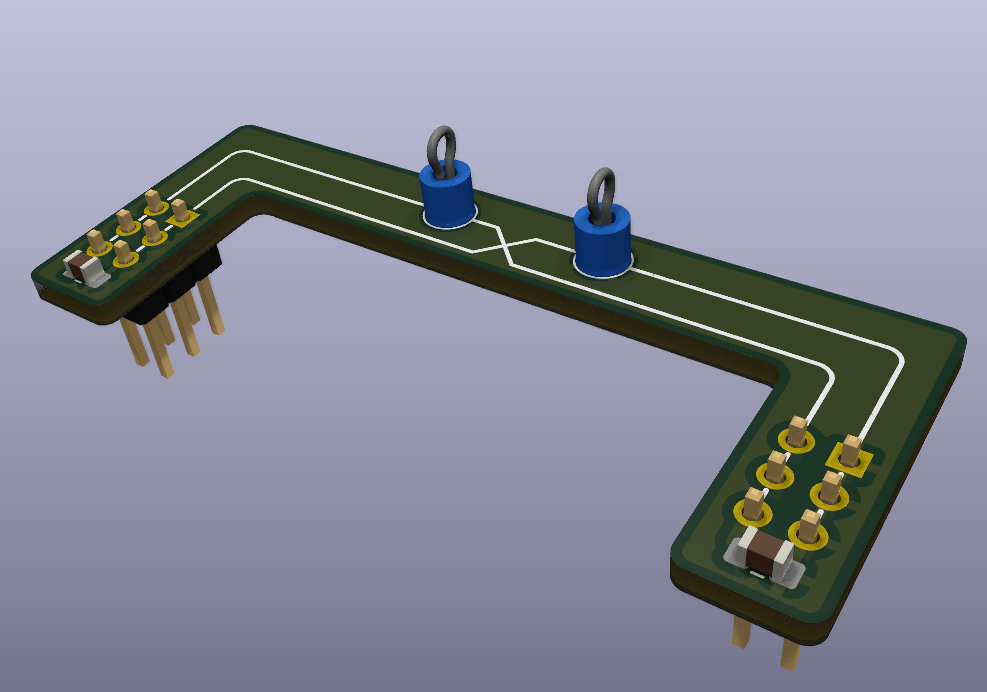
I liked IMSAI Guy’s design with the exception that the homemade clip points looked messy and I knew that Keystone had off the shelf test points that would work perfectly.
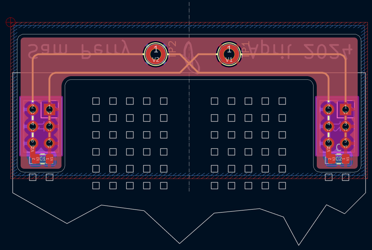
There is not much to this project. Soldering it together is super simple, place the 6 position 2 row male headers in a breadboard to hold them in position while soldering. Then solder one red and one black test point on. Optionally a 0.1uF 0805 capacitor can be solder on each side for power supply decoupling, be sure the use a capacitor with a voltage rating higher then you would build breadboard circuits with. I chose a 50V rated capacitor which is more then double what I normally connect to a breadboard.
BOM
| Item | Description | Quantity | Notes |
|---|---|---|---|
| PCB | Gerbers are in the GitHub repository | 1 | manufactured by PCB prototyping service of choice |
| Test Point | Keystone Electronics 5280 | 1 | red |
| Test Point | Keystone Electronics 5281 | 1 | black |
| Male Header | Adam Tech PH2-06-UA | 2 | any similar 6 position 2 row male header will work |
| 0.1uF 0805 Capacitor | 2 | Optional or maybe 10uF |
All design files can be found in my GitHub repository.

