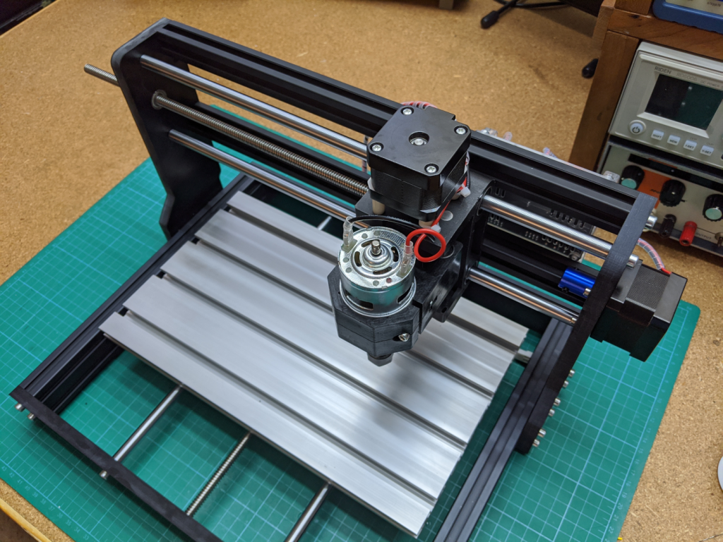
The CNC 3018 Pro Router (called 3018 pro for the rest of this article) does not come with endstops. While not required for use I wanted to add endstops to enable homing and as a safety for making sure the 3018 pro does not try to go outside of its bounds.
The Switches
For limit switches I chose the Omron SS-5GL2 mainly because I had enough of them on hand. Lower cost versions of these switches can be purchased from the usual low cost component suppliers such as AliExpress, eBay, and LCSC. Some of them may not be actual Omron switches but it is the form factor that matters. Wherever you get them you will need at least 6 but get a few spares just in case.
STL Files
I have uploaded all the STL files ready for 3D printing to Thingivers, PrusaPrinters, and GitHub. The source FreeCAD files have also been uploaded. For print settings I used 3 perimeters and 3 top/bottom layers, 15% gyriod infill, and PETG filament. These parts are not seeing much load so the settings are not critical but I highly suggest printing these parts with PETG, it is a better material for mechanical parts like these. No supports are needed as long as you print the parts as they are oriented in the STL files.
Disassembling the 3018 pro
While the parts are printing the 3018 pro needs to be dissembled slightly to make installation of the hardstops easier. Unplug the spindle motor and z stepper from the control board. Disconnect the x leadscrew from the x stepper, turn the x lead screw so that it moves away form the x stepper and pokes out the left side. Keep turning the x lead screw to unthread it from the spindle carriage and remove it from the machine. Remove the M5 bolts holding the 10mm linear rods for the x axis and the spindle carriage should drop out of the machine. Remove the linear rods from the carriage assembly for now.
disconnect x leadscrew 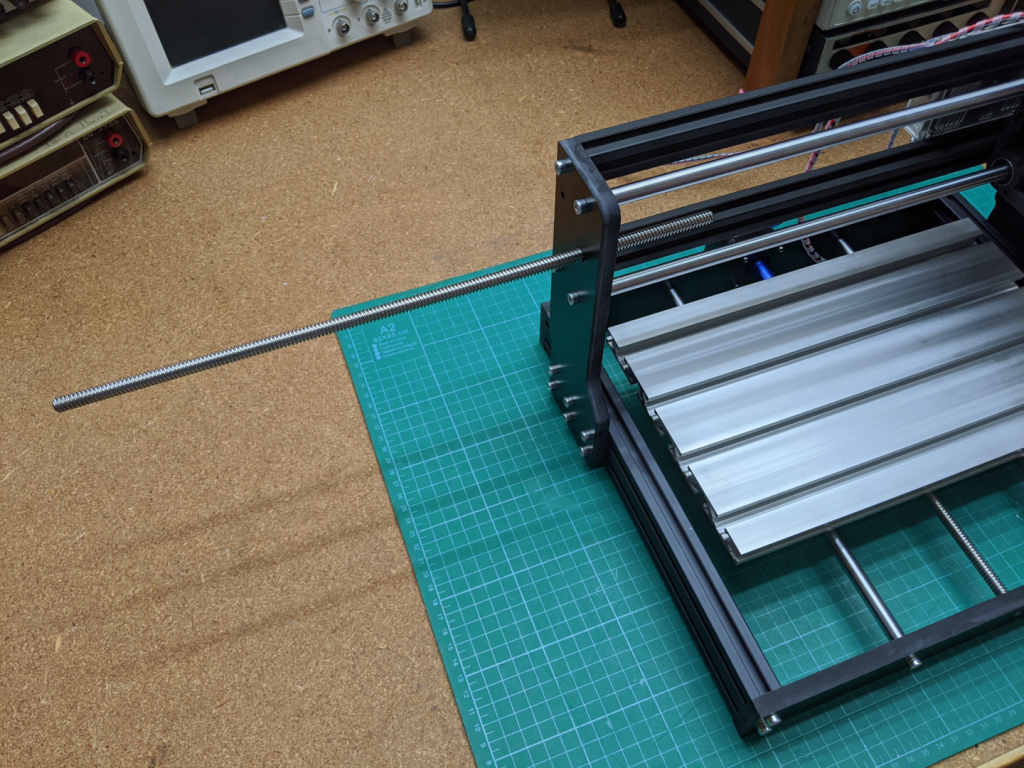
pull out through left side 
remove linear rails 
spindle carriage free
The X Axis
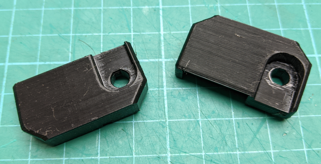
This is the easiest axis to add endstops. Print the x_positive and x_negative switch mounts.
Solder wires to two of the limit switches on the common (C) and normally open (NO) terminals. I used 24AWG of different colors but anything close to that will work and they can all be the same color. Make sure the wires are long enough that when mounted they can be connected to the controller. The wire on my x_negative switch is about 60cm long and will be cut to length when it is mounted. The wire for the x_positive is the same length (I am cutting up a wiring harness from something I salvaged) but can be much shorter depending on the placement of your controller.

Insert the switches into the printed mounts, note the orientation of the switch lever. There are two bumps in each of the printed mounts that should fit into the holes on the switch to help locate it.

Use a M5 10mm bolt and a drop in tee nut to mount each of the switches on the extreme ends of the bottom aluminum extrusion supporting the x axis. Note the orientation of the switch levers.
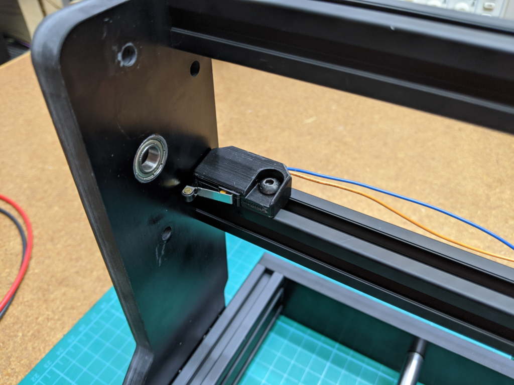
x negative switch in position 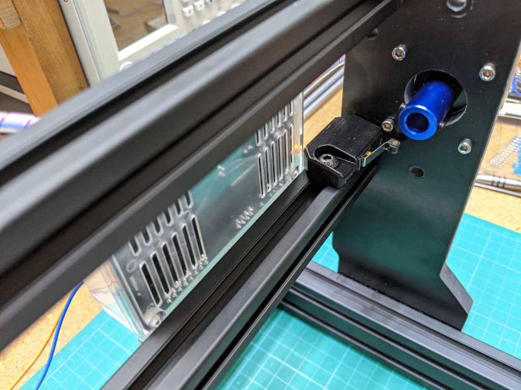
x positive switch in position
Cut the wires to length so that the will reach the X-Limit header on the controller board, leave some slack in the wires. Crimp on female connectors for the header pins then connect the limit switches to the board. A quick note on the limit switch header, looking at the schematic for the Woodpecker V3.4 I discovered that the two top pins for the x-limit header are connected together, this is the same with the other axis limit headers pins. So the order you connect the limit switches to the controller doesn’t matter, as long as the x-limit switches are connected to the 3rd and 4th column from the left.

The Y Axis
This axis is about as easy as the X axis. Print the y_negative, y_positive, and y_trippers. The y_negative and y_positive are the same part so you can print two of either. Early on in the design I was going to make them slightly different from each other but decided against that.
The y endstops are mounted on the right side of the 3018 pro. It is easier to work from the bottom side of the machine.
I didn’t have any tee nuts that fit the tracks of the 3018 pro’s bed so I designed my own tee nuts that use the M5 drop in tee nut as the threaded fastener since I also didn’t have any M5 hex nuts. Print two 3030_tee_nut if you also don’t have tee nuts for the bed.

Mount the y tripper in the center slot on the bottom of the bed, this is the same slot that the y leadscrew nut is attached to. Again working with the machine tipped upside down makes this much easier. Use the 3030 tee nuts in the above photo if you don’t have any. For bolts I used two M5 x 16mm flat head hex bolts. Using a ruler make sure there is at least 1mm of clearance between the tripper and the side of the frame.

Solder wires to the C and NO pins of two switches. Make sure the wires will be long enough to reach the controller when they are installed. Again 60cm should be more then long enough for the y positive limit switch and the y negative limit switch can be much shorter. We will trim the wire to length after the switches are mounted.
Insert the the switches into the y switch mounts and using M5 bolts and drop in tee nuts mount them to the side of the frame that the y tripper is nearly touching. Working from the underside of the machine is easiest. Make sure to orient the wires and switch levers as shown in the photos.

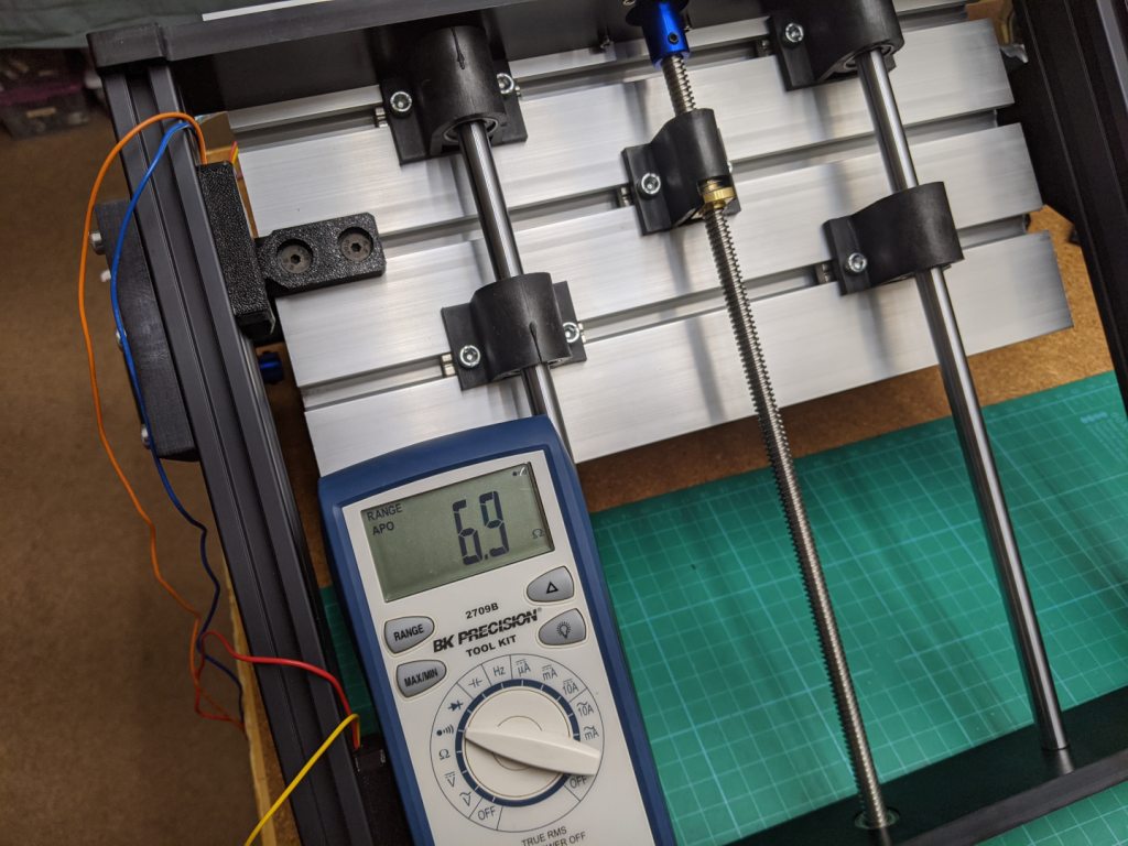
Move the bed of the machine all the way to the front of the machine, leaving a little space between the linear bearing mounts and the front of the machine frame. Attach a multimeter set to continuity mode to the wires of the limit switch and slide the limit switch towards the y tripper until the meter sounds. Tighten down the switch mount and then move the bed so that it is not activating the limit switch before moving it back to activate the limit switch to check the placement of the limit switch. Do the same procedure for mounting the y negative switch.

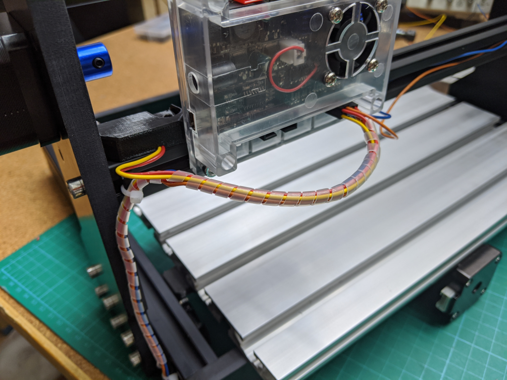
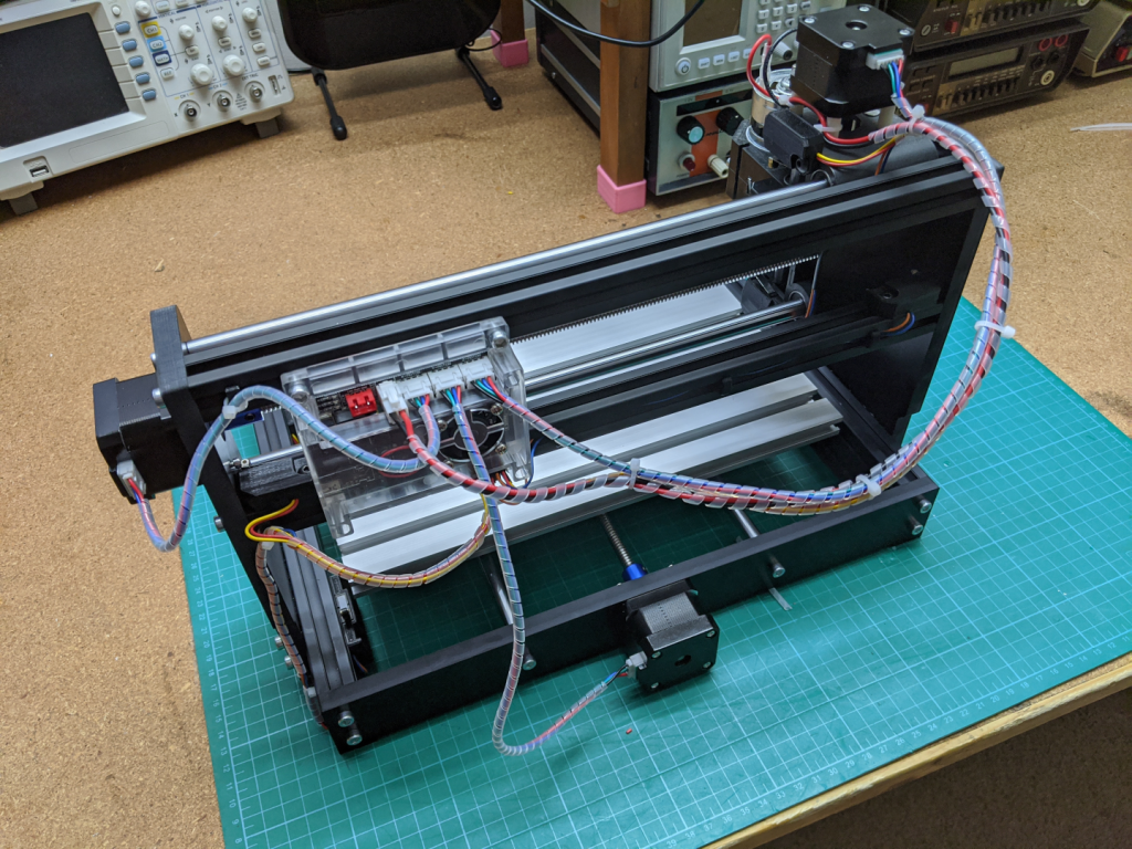
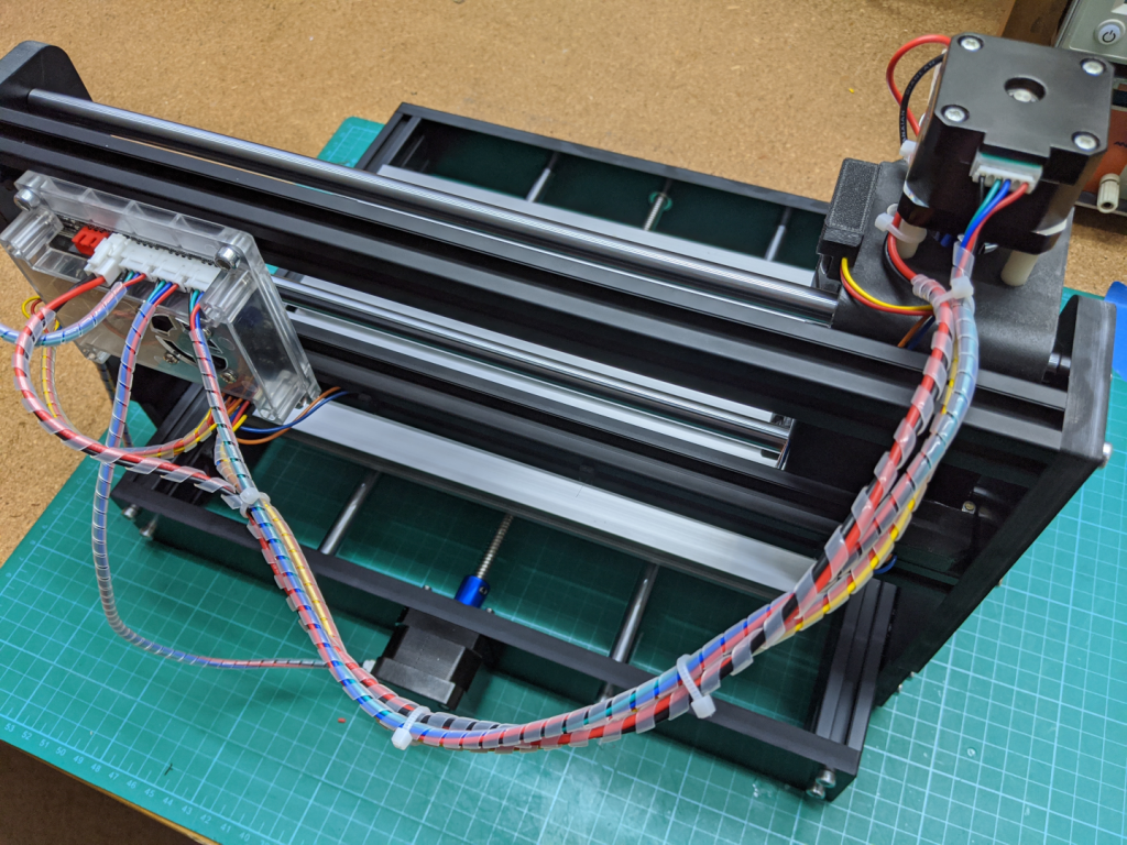
Flip the machine so that it is upright again. Trim the wires so that they have just enough slack when plugged into the Y-Limit header on the controller PCB and crimp on female header connector pins. Don’t route the wires through the back of the frame such that the bed will pinch them when it travels to the y negative extreme. I will leave wire wrangling up to you since everyone has their own preferred method. I used the cable_clip_ziptie from the Prusa Bear upgrade to hold the wires in the track on the bottom of the frame and then to tie them to the side of the frame. I bundled the wires in 3mm diameter spiral wrap.


The Z Axis
Mounting the Z axis endstops requires the most modification, you will have to drill and tap a total of 4 holes in the spindle carriage.
Print the z_negative, z_positive, and z_trippers using the same filament type and settings as the x and y axes.
Cut 4 lengths of 24 AWG wire about 60cm long. Thread 2 wires through the wire holes on the z_positive and and 2 wires through the holes on the z_negative switch mount. You may have to open these holes up with a drill bit if the wire doesn’t fit nicely. Solder the wires to the C and NO pins of the limit switches before placing the switches in the holders.

The limit switch mounts attach to the carriage using two holes that are already in the plastic near the linear bearings. These holes are already about 3.95mm in diameter but need to be opened up so we can tap them for a M5 bolt. Referencing a metric tap drill chart I am going to use a #19 drill. There is no need to drill to a depth of more then 10mm. Double check the drill size is correct before drilling, you only get one shot at this. Tap both holes for M5-0.8mm. Mount the switches using M5 bolts. Remember that we are threading into plastic so go easy on the torque.


drill 
tap 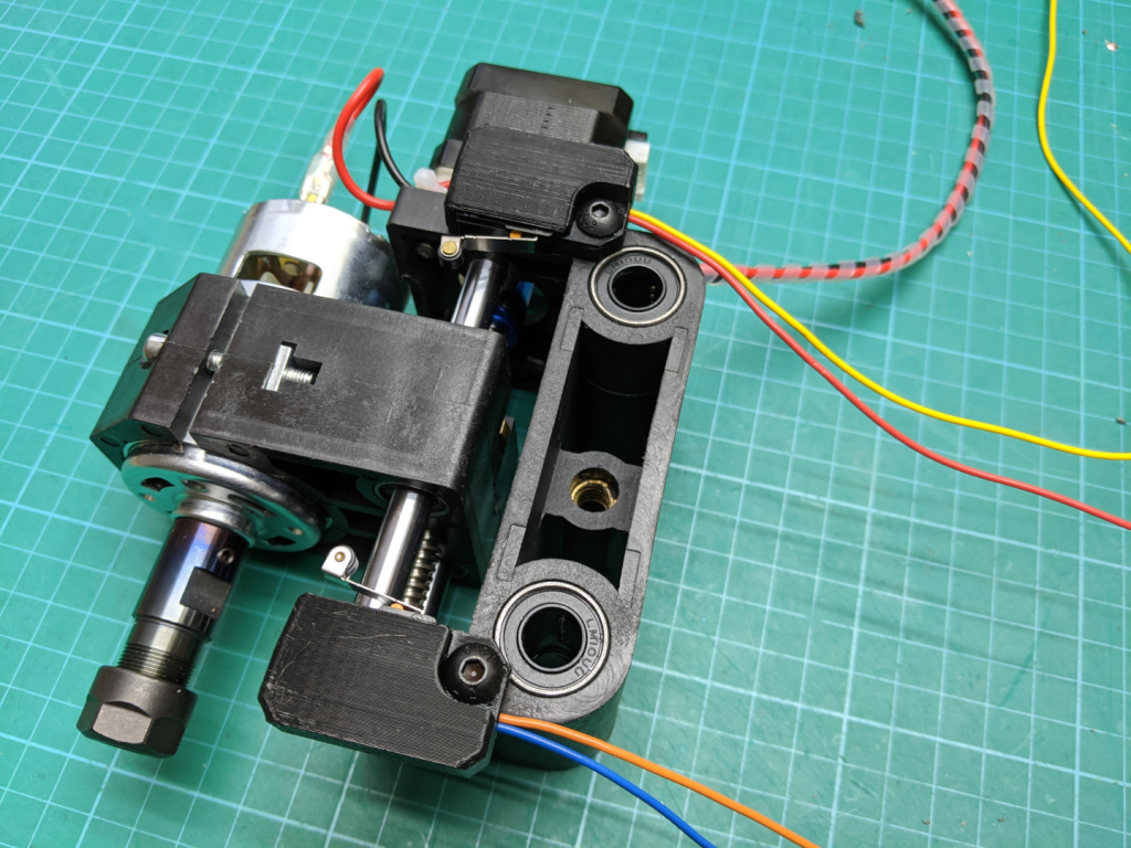
mount
Now to mount the z_tripper. This requires drilling and tapping two holes in the right side of the spindle mount. First place the z_tripper on the side of the part, there is a lip on the bottom and back side of the part that will help with placement. Whenever I am mounting something like this I prefer to mount it one hole at a time so using a drill or bolt mark the top hole only. Using a M3 tap drill make a hole all the way through the plastic into the hollow behind it, about 4mm. If possible use a drill press to get this hole perpendicular to the surface. Tap this hole for a M3-0.5 bolt. Bolt the z_tripper on and then mark the bottom hole, drill and tap this hole the same as the top hole. With both holes threaded mount the z_tripper using a 8mm long M3 bolts. Again since this is threading into plastic don’t over torque the bolts.


mark top hole 
drill top hole 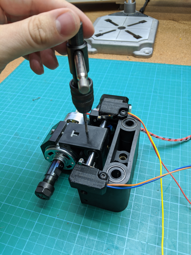
tap top hole 
mount using top hole, mark bottom hole
Mount the spindle carriage to the 3018 pro using the same steps you used to remove it but in reverse. Move the spindle to the far left. Trim the limit switch wires to length leaving a little bit of slack and crimp on female header pins. Connect the wires to the Z-Limit header pins on the PCB. Tidy up the wiring.


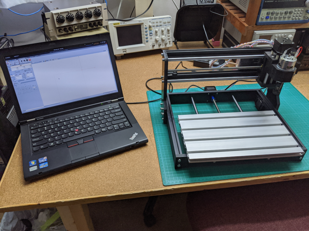
The GRBL
We need to configure the machine to use the endstops now and this requires sending a few configuration commands to the GRBL controller. Connect the the 3018 pro using your PC and favorite GRBL controller program, I am using bCNC.
Open up the command terminal and send the following configuration commands one at a time. Comments are after the ; and can be omitted when sending the commands.
$5=0         ; limit pins are active low
$20=1        ; enable soft limits
$21=1        ; enable hard limits
$22=1        ; enable homing cycle
$23=0        ; home towards X+, Y+, and Z+
$24=25.000   ; homing feed, mm/min
$25=100.000  ; homing seek, mm/min
$26=25       ; homing debounce, milliseconds
$27=1.000    ; homing pull-off, mm
$130=285.000 ; X Max travel, mm
$131=177.000 ; Y Max travel, mm
$132=41.000  ; Z Max travel, mm
Restart the GRBL controller on the 3018 pro and reconnect to the PC. Test all the switches before continuing by manually triggering them. This should trigger an alarm for each of the switches, if not then double check your configuration commands and wiring. Now send the home command $H. It was at about this moment when I realized that the X-Limit and Z-Limit pins were switched, it seems like the silkscreen on the controller is wrong so if when you home you find that your z axis ignores the z limit switch but manually pressing a x limit switch triggers it then swap the pins.
All files can be found in one of three places: Thingivers, PrusaPrinters, and GitHub

Great work! Is still working! Thx a lot!
LikeLike
This guide and STL’s are excellent, still works on CNC 3018 Pro Max! Thanks a lot, time saver!
LikeLike
I get error codes when entering the g codes per your article. What do I do now?
LikeLike
I am not sure. Check out the Grbl Wiki: https://github.com/gnea/grbl/wiki
LikeLike
Brilliant, thank you so much for this tutorial.
LikeLike
What is the best for connecting the wires to the board? Dupont-connectors?
LikeLike
Yes
LikeLike
These T nuts are easy to find on Amazon; just look for Tee Sliding Slot Nuts 30 Series M5.
The technical name is “T Nuts M30-M5”
Fantastic your tutorial BTW
LikeLike
M5 taps are hard to find. For anyone in the US, I used #8 3″ screws to mount the Z stops to the spindle carriage. 2 3/4″ would have been better, but it’s what they had. I added a nut to each side to take up the extra length so the extra length didn’t hit the sides of the uprights. M5 taps are hard to find. I CA glued the Z trigger in place. It works for now. It it breaks I’ll do something like drill into the spindle carriage.
LikeLike
An elegant design, well executed. Thank you for sharing the STLs and description.
LikeLike
I loved the simplicity of your endstops for the 3018 BUT I could not find the STL files on thingivers.
the link goes to much more complex designs? There are 310 files of more complex designs.
How do I find the ones described in your presentation?
Fantastic job really show clear installation photo’s
LikeLike
Did you use the link in the “STL File” section at the top of the page? Works for me. Here it is again: https://www.thingiverse.com/thing:4566506
LikeLike
4566506 goes to a new design? Not the design described in cnc-3018-pro-router-qdding endstops?
LikeLike