Psst! Looking for more? Check out the Tronxy P802M page with links to other articles about modifying and improving the Tronxy P802M 3D printer.
Inspired by a YouTube video I decided to upgrade the controller on my Tronxy P802M from the Melzi 2.0 8 bit controller to a 32 bit BIGTREETECH SKR V1.3 controller. Below is a guide for anyone else looking to upgrade the controller on their Tronxy P802M to the SKR V1.3.

Hardware
Remove Old Controller

Before removing the old controller label all the wires to avoid having to trace the connections later. You will also want to cut any cable ties holding down the wires near the old controller since the wire routing will have to change to match the layout of the new controller.

Disconnect the wires from the old controller and completely remove it from the printer. We don’t need anything on the old controller so it is available to use in a new project.
Read New Controller User Guide
It is helpful to read the user manual and look at the documentation provided by the manufacture of the SKR V1.3 before proceeding. The manufacture of the SKR V1.3 has uploaded a user guide and some useful diagrams to their GitHub repository:
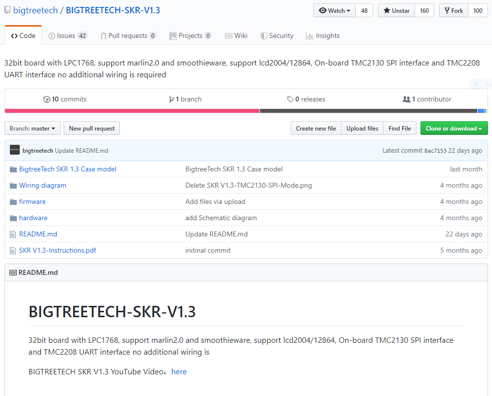
This repository will be helpful if you chose to use slightly different hardware then outlined in this guide.
Installing the Stepper Drivers
Before mounting the SKR V1.3 controller you will need to install the stepper drivers. I got A4988 drivers when I ordered my board so my hardware and software setup will be for using those drivers. If you got different drivers you will have to set them up differently then what is outlined in this guide.
It is important to set the jumpers that will be hidden by the stepper drivers before installing the stepper drivers on the SKR V1.3. These jumpers set the microstepping resolution of the stepper motor. Your board probably shipped with all the jumpers installed so the first step is to remove all the jumers except for the one shown in the photo below. This jumper sets the 5V bus power to be derived from the onboard 5V regulator or from the USB connector. Set this jumper to INT for now as shown in the photo.

The jumpers to set a microstepping resolution of 1/16 are shown below and are what this guide will assume you set your jumpers to. If you want a different microstepping resolution set the jumpers according the the table below but you will have to adjust the controller firmware for your step resolution.

| MS1 | MS2 | MS3 | Microstep Resolution |
|---|---|---|---|
| Low | Low | Low | 1/1 |
| High | Low | Low | 1/2 |
| Low | High | Low | 1/4 |
| High | High | Low | 1/8 |
| High | High | High | 1/16 |
*Install jumper to set it as high.
Next let’s install the stepper drivers. Be sure to note the pinout of the stepper drivers and the pinout of the SKR V1.3 to make sure you get the orientation right. The photos below are for reference but check the pinout before you install them. The SKR V1.3 has all the pins labeled on the bottom of the board to make confirmation of orientation quick and easy. Don’t forget to install heatsinks on the driver ICs, these will get hot and need all the cooling they can get. Install the heatsinks oriented as shown since the controller will be mounted in a later step with the heatsink fins vertically to increase cooling.

Now is a good time to set the current limiting of the stepper drivers. Without connecting stepper motors to the SKR V1.3 power the board using a 12V power supply. The current limiting is set by adjusting the potentiometer on top of each stepper driver which sets Vref.

Vref is related to the maximum current by the following equation:
Vref = 8 * Imax * Rcs
Rcs is the resistance of the current sense resistors installed on the stepper driver PCB, this is 100mΩ on the drivers shown here. The stepper motors on the Tronxy can handle up to 1.68A of current but to be safe we will set the current limit to 1A. Therefore Vref should be set to 0.8 volts. Vref is measured by touching the multimeter probe to the top of the potentiometer as shown. This will require you to measure Vref, adjust the potentiometer slightly and then measure again. Aim for close to 0.8 volts but dont go crazy, 0.818 volts is close enough.

Mount Controller to the Tronxy Frame
Time to mount the SKR V1.3 to the Tronxy P802M frame. This is simple since some of the pre existing holes on the Tronxy P802M frame line up nicely with the mounting holes on the SKR V1.3. Missing holes can be easily drilled into the acrylic frame. The following mounting was accomplished using all but one pre existing hole, the lower left hole was added. Use the same mounting hardware as used to mount the old controller you just removed, M3 bolts with nylon spacers. Orient the board as shown so that the USB port and microSD card can be easily accessed.

Connect Wires
Wiring the board up is simple and requires little modifications of the existing Tronxy wire connectors. The below diagram provided by the manufacture outlines the available connections. We will go step by step though where to install each wire below.

- Connect 12V power from the power supply to the DC12/24V POWER IN terminal. Observe correct polarity, the top pin of the terminal block is +.
- Wire the bed heater leads to the terminal labeled BED, polarity is not important.
- The hot end heater is wired to E0 Heater
- Connect the x stepper motor to X-Motor
- Connect the y stepper motor to Y-Motor
- Connect one of the z stepper motors to Z-Motor, connect the other z stepper motor to E1-Motor
- Connect the extruder stepper motor to E0-Motor
- Plug the bed terminster into the connector labeled BED Thermistor shown at the bottom right corner of the diagram
- The hot end thermistor connects to E0 Thermistor
- The x axis endstop connect to the upper left 4 pin connector that is labeled as End Stop in the connection diagram. The silkscreen label next to this connector is X-
- The y axis endstop connects directly below the x axis endstop. The silkscreen label next to this connector is labeled Y-.
- Finally the z axis endstop connection is below the y axis endstop and is labeled Z- on the silkscreen.
The polarity of the extruder fan and the layer cooling fan connectors need to be swapped before they are installed. Use a sharp object such as an exacto knife to remove the pins from the connector housing and then reinsert them in the opposite polarity. If you need help on how to swap pins watch this helpful and quick YouTube video from user Ilia Brouk.

Connect the fans as follows. The layer cooling fan plugs into the connector labeled CNC FAN. The extruder cooling fan plugs into the 12V/24V OUT connector at the top left of the wiring diagram.

The below picture shows the controller fully wired after a little cable management.

Last we need to address the LCD and user input buttons. I was unable to get the original Tronxy display and buttons to work with the SKR V1.3, the new controller doesn’t have a connector that matches that LCD. The easiest thing to do is to purchase a cheap LCD and the RepRapDiscount Smart Controller is the lowest cost LCD with user input that I could find from the usual suspects. The LCD connects to the SKR V1.3 connectors labeled LCD-EXP1 and LCD-EXP2. The RepRapDiscount Smart Controller has connectors labeled EXP1 and EXP2 on the back of the display that are a pin for pin match the the connectors on the SKR V1.3. As an added bonus the display has an onboard SD card connector so we can load the files to print using this easier to access SD card.
After the printer is fully assembled we will print a case to hold and mount the new LCD but for now it can be left sitting next to the printer. The old LCD can be removed and repurposed.

With the SKR V1.3 connected to the printer hardware it is now time to setup the firmware of the controller to work with the Tronxy P802M hardware. Don’t turn on your printer just yet.
Firmware
Don’t want to compile your own firmware? You can download a compiled version for the Tronxy P802M as long as you are using the exact same hardware from my GitHub repository. Copy the firmware.bin file included in that repository to the microSD card that came with the SKR V1.3. On powerup of the SKR V1.3 the firmware will be updated. Jump to the Testing section of this guide since you don’t need to know how to compile firmware.
Installing Required Software
The SKR V1.3 uses Marlin 2.0 as the firmware. The manufacture of the SKR V1.3 does supply in their GitHub repository a copy of Marlin 2.0 but it will not be setup to run the Tronxy P802M hardware configuration. We will start with a fresh copy of Marlin 2.0 which is bugfix-2.0.x at the time of writing this guide. First we will have to install an IDE that will allow us to edit and compile the code for the SKR V1.3.
If you don’t have Visual Studio Code (VSC) installed do so using the link below. VSC runs on most operating systems including Windows, Mac, and popular distros of Linux.
https://code.visualstudio.com/Download

We will now need to add an extension to VSC to be able to open the Marlin 2.0 firmware and compile it for the SKR V1.3, PlatformIO. This link below will take you to an installation guide for adding the PlatformIO extension to VSC. The image below is a screenshot of that page for quick reference.

Marlin 2.0
Now we are ready to download and configure Marlin 2.0. Do so using the link below. The current version of Marlin at the time of writing this guide is bugfix-2.0.x but a newer version maybe available so check the Marlin download page.

Unzip the file you just downloaded and open VSC if you have not done so already. Now we are going to open up the Marlin 2.0 project file, click the PlatformIO: Home icon in the lower left of VSC if PlatformIO did not pop up when you opened VSC. Chose Open Project and navigate to the Marlin 2.0 folder that you just unzipped and open it.

With the Marlin 2.0 firmware opened in PlatformIO we are now prepared to modify the configuration files so that we can compile firmware that will work with the Tronxy P802M hardware and the SKR V1.3 controller.
I have setup a GitHub repository that will contain the configuration files so you do not have to modify them yourself. I suggest looking through the files since it will be helpful if later on you want to modify the Tronxy P802M hardware but it is not necessary. You can just copy and paste and be done with it. Download the modified configuration files at the link below.
https://github.com/sdp8483/Tronxy_P802M_SKR_V1-3
Replace the following files in the Marlin 2.0 project folder with the files downloaded from the Tronxy_P802M_SKR_V1-3 repository:
platformio.ini
/Marlin/Configuration.h
/Marlin/Configuration_adv.h
Open platformio.ini in VSC and make sure that default_envs = LPC1768
Finally we are ready to compile the code. Press the PlatformIO: Build check mark at the bottom of VSC. A console will popup and after awhile should end with a succeeded message as shown.

Remove the microSD card installed in the SKR V1.3. Insert the card into your PC and wait for confirmation that it has been read by your computer. In VSC next to the check mark we used to compile the code is an arrow pointing right, the PlatformIO: Upload button. Clicking this should upload the code to the microSD card. If this doesn’t work you can navigate to /.pioenvs/LPC1768 in the Marlin 2.0 project folder and manually copy the firmware.bin file to the microSD card
The microSD card will then contain two files, firmware.bin is the new firmware we just compile and FIRMWARE.CUR is the firmware that is currently installed on the SKR V1.3. Remove the microSD card from your computer and insert it into the SKR V1.3. On powerup the new firmware will be loaded onto the controller.
Testing
Power up the Tronxy P802M. Jog all three axis to make sure that their direction is correct. Then home all three axis to make sure that the homing switches are working. Be ready to quickly power off the printer is something goes wrong.
Check the hotend and bed temperature readings and make sure that they are reading a reasonable temperature for your current room temperature, somewhere around 23°C.
If any of the above tests result in a failure then you hardware is not exactly like the hardware on my Tronxy P802M printer. You will have to read through the configuration file /Marlin/Configuration.h and make the appropriate changes. It’s a large file but should contain everything needed to configure your printer correctly. If you cannot find the setting there then /Marlin/Configuration_adv.h contains even more settings.
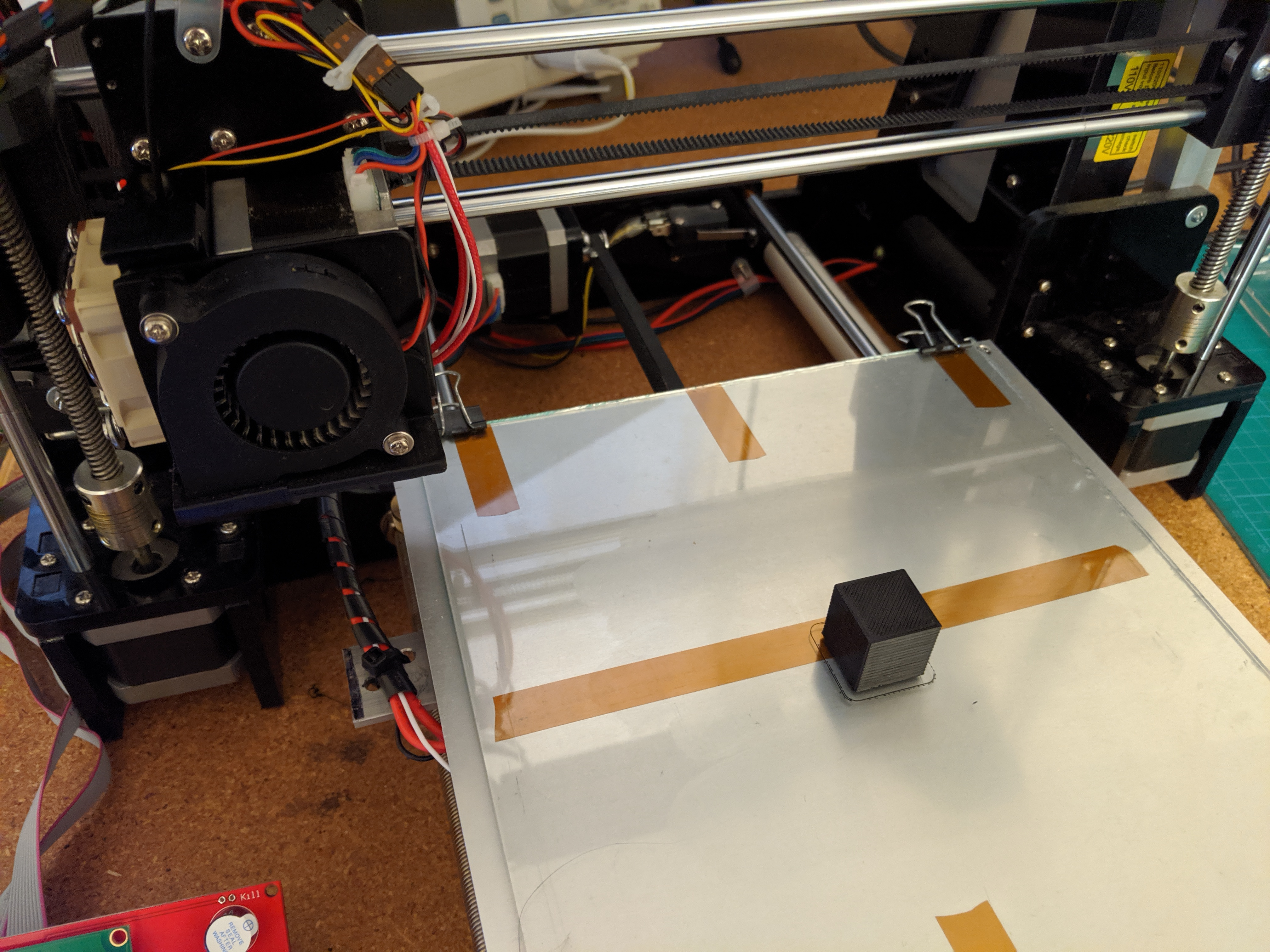
Now print something! Try a calibration cube to make sure the steps/mm for all three axis is correct.
LCD Case
The LCD used for the Prusa I3 Mk3 is the same as the RepRapDiscount Smart Controller LCD that we upgraded to. Therefore the case designed for the Prusa I3 Mk3 will work perfectly to house the LCD for the Tronxy P802M. Download the files from Prusa at this link. Print the LCD-cover-ORIGINAL-MK3.slt and lcd-supports.stl files. To mount the LCD will reqire a few new holes be drilled in the frame at the place of your choosing. The cables that came with my LCD were to short so I had to make up two longer cables to reach my mounting position.

Want more? Check out the Tronxy P802M page with links to other articles about modifying and improving the Tronxy P802M 3D printer.

I bought same hardwares what you use and did copy and pasted Firmware.bin from tronxy Stock folder to sd card then plugged it in sd slot on new BTT SKR 1.3.
One question, about rep rap display screen with two cables. Can I use BTT mini 12864 v 1.0 voron rep rap GLCD display with two cables.
Thanks
LikeLike
If you would like to use another display then the best thing is to modify Marlin and compile the firmware. I would suggest getting the latest version of Marlin from their website. Read through “Configuration.h” and “Configuration_adv.h” and modify for your needs. You can follow the config files I have to find what settings to use for the hardware you have (minus the different LCD).
LikeLike
Ok, I think I found the file deep in Configuration.h and it says 12864 (basically same as reprap display that you have on your machine.) I also will check on Configuration adv.h too… I haven’t figured how to compile it to .BIN file. I copied .bin from Tronxy folder and flashed it to new board long before I comment today.. I think you already explain 3 Tronxy files needed to be merged into Marlin 2.0. ( I merged 6 files according to picture below it which is why I got error message on MS VS after compile) I know I have to remove “#” to enable it (I have done so on Ardurino projects) If I can’t get it to work, I would be happy to order same kind of display that you have (they’re cheap as BTT display, bought it for $20 buck) in order to get it working. I am able to test run printer with no display on Octoprint and also connect to my laptop using Cura or Repitier Host server, Both works great but having issue with extruder, it extruded skinny filament. Settings in Cura and Repetier Hose have limited options, no feedrate to tweak, I even tried on Octoprint to adjust feedrate, no avail.. I don’t know what I did with settings (never had issue on old Meltz board for a year until few weeks ago, somehow I jinx the settings, assuming that Driver chipset went bad for extruder even swapped the stepper motor, same result so I replaced with SKR 1.3. with Marlin flashed into it. still same result). I did changed out hotend as well and checked temp using thermal thermometer, look ok.. but still skinny… When I release filament extrusion gear and push filament in like it was before jinx, It extruded like normal during print. Look like I have to fix feedrate which is why I am trying to get new display working so I can tweak it. Upon my observation, feedrate seem going slow. I saw in youtube that guy use ruler and he explain how to measure extrusion by cutting filament at extruder end and run it. if extruder stops at 5mm, need to increase speed and once it reach 10mm. It’s fixed. so that’s my plan. I believe that old board is working fine, I would keep it as a backup and perhap fix the feedrate via Repitier Host. But I love new board and noticeable smooth and faster. I intend to keep new board on and work on configuration and save it to BIN file. I do have Arduino IDE as well as MS Visual Studio. Thanks
LikeLike
Correction on display, I mentioned about 12864 same as yours, I’m wrong. it’s 2004 display, not 12864…, recently ordered for same price as BTT. should get it in few days. thumb up..
LikeLike
Got rep rap discount smart screen and all works and able to mess around settings! As for extruder issue. I got it figured out. Now it’s working great except nozzle temp overrun so I have to tweak temp. settings and fix the themoresistor (it’s working but think it’s not deep enough). Now, I figure out that I can switch to BTT 12864 screen by configure using fysetic 12864 which is similiar to BTT on Marlin.
Thanks a ton!
LikeLike
I’m looking for an upgrade kit at eBay and there are several options. I see the SKR V1.3 are available, can a later version work with my Tronxy P802M? Also the stepper drivers, what version will work with the SKR V1.3? I see a lot of versions: 2130, 2208, 2209, 8825?
Appreciate the help in advance in upgrading from 8 bit to 32 bit. Thank you.
LikeLike
I think the SKR V1.4 is a drop in replacement (you have to set the new board version in Marlin). The other BTT versions I am not so sure. I use TMC2130 for sensorless homing and they are nice. I also have the TMC2209 on another printer and I like them too. If you have homing switches go for the TMC2208 if they are cheaper since they don’t support sensorless homing. I am not sure about the 8825. Pick up an A4988, I have issues with using the trinamic drivers on the extruder and found using the good old A4988 on all my printers helps.
LikeLike
Hi Sam,I am ready to upgrade the motherboard on my Tronxy P802M, same with what you have on your web page. However I will be using a different display, TFT35 touch screen.Following the steps and back tracking numerous times. I cannot quite compile the new firmware using the PlatformIO and getting multiple errors in the process.Please advice, I have the same motherboard as you have (SKR v1.3) and TMC2208 stepper drivers. You can just send me your compiled firmware and I can just load it for my upgrade.Thank you for your help in advance.Ron M.
LikeLike
Good Morning Sam,I figured it out. Thank you very much.Ron M.
LikeLike
I use 4988 drivers, I see 8825 as good subsitute ( both have pot to adjust voltage for stepper). But using 8825 requiring you to configure Marlin. What I did order exaclty what Sam Perry have and use Tronxy.bin that I downloaded and copied to SD card then flashed update it. It works perfectly and suggest you to get Rep Rap Discount Smart screen as well (I do have BTT 12864 mini screen which didn’t work because I haven’t configure Marlin myself, will figure it out in future and swap it out once I got it). So that would save you alot of trouble if you are not quite familiar with configuring marlin on Visual Studio. Save your time and trouble.. If you can do configuration on Marlin and flash it to BTT SKR 1.3 or SKR 1.4, then you can do more to upgrade other hardwares as well. I’m just keeping setup simple for myself because I’m still a bit of noob. LOL
LikeLike
would this method (more specifically firmware) work on a p802ma? i believe its the same printer just with a prox sensor and auto level comp.
thanks, love your write up!
-Bruce
LikeLike
Yes it would. Search the configuration.h file for auto bed leveling to enable it and to set up the probe you are using. I have since added a probe to my printer and it was easy to enable.
Z probe option starts at around code line 824
Bed leveling is around code line 1191
There are a few more setting you may have to set if I remember correctly so just scroll through the config file and the advance config file and read the comments. There should also be many good guides on YouTube to guide you.
Thanks!
LikeLike
tengo un problema con el problema con el programa. no tengo conocimiento ni experiencia en programación pero he seguido tu guía y a la hora de verificación PlatformIO: me sale LPC1768 FAILED 00:00:00.724 .
Llevo un mes intentando arreglarla y esta es la única guía que he encontrado.
LikeLike
I have followed your “tronxy-p802m-controller-upgrade-to-32-bits”, and have a unexpected problem, I do not get any filament feed _when printing_. When using the repetier-host manual control on my pc the filament feed works ok. I have used your firmware.bin (I have a bog standard p802M) from github.
Do you have any ideas what the problem can be?
(if I can`t figure it out, I return to the default contoller..
Yours
Anders Frihagen
BTW your article is just brilliant!
LikeLike
That is a strange problem. Look at your gcode that your slicer program is outputting and check to make sure that extrude feeds in the gcode are similar to what the Marlin documentation shows: http://marlinfw.org/docs/gcode/G000-G001.html
Otherwise try to compile the firmware yourself and give that a try. If it works with repetier-host it should work when printing from SD.
LikeLike